Non-contact measurement systems for wireline and coiled tubing

Active Publication Date: 2010-04-22
NAT OILWELL VARCO LP
View PDF41 Cites 24 Cited by
  • Summary
  • Abstract
  • Description
  • Claims
  • Application Information

AI Technical Summary

Benefits of technology

[0011]In certain aspects, the present invention discloses apparatus and method with sensor(s) that do not touch a wireline cable or coiled tubing being measured. In certain particular aspects, a relatively small size system is used that allows for advantageous positioning of the equipment. Also, the present invention discloses me

Problems solved by technology

Several of such known depth measurement systems suffer accuracy and repeatability problems that manifest themselves as an inability to correctly record the depth of a leading end of a wireline cable or coiled tubing in the wellbore.
Repeatability problems are often caused by an undetermined amount of slip which results when cable or tubing passes measurement wheels without an equivalent rotation of the measurement wheels being recorded.
Repeatability errors often are due to the inability of existing depth measurement system

Method used


Image

  • Non-contact measurement systems for wireline and coiled tubing
  • Non-contact measurement systems for wireline and coiled tubing
  • Non-contact measurement systems for wireline and coiled tubing

Examples


Embodiment Construction

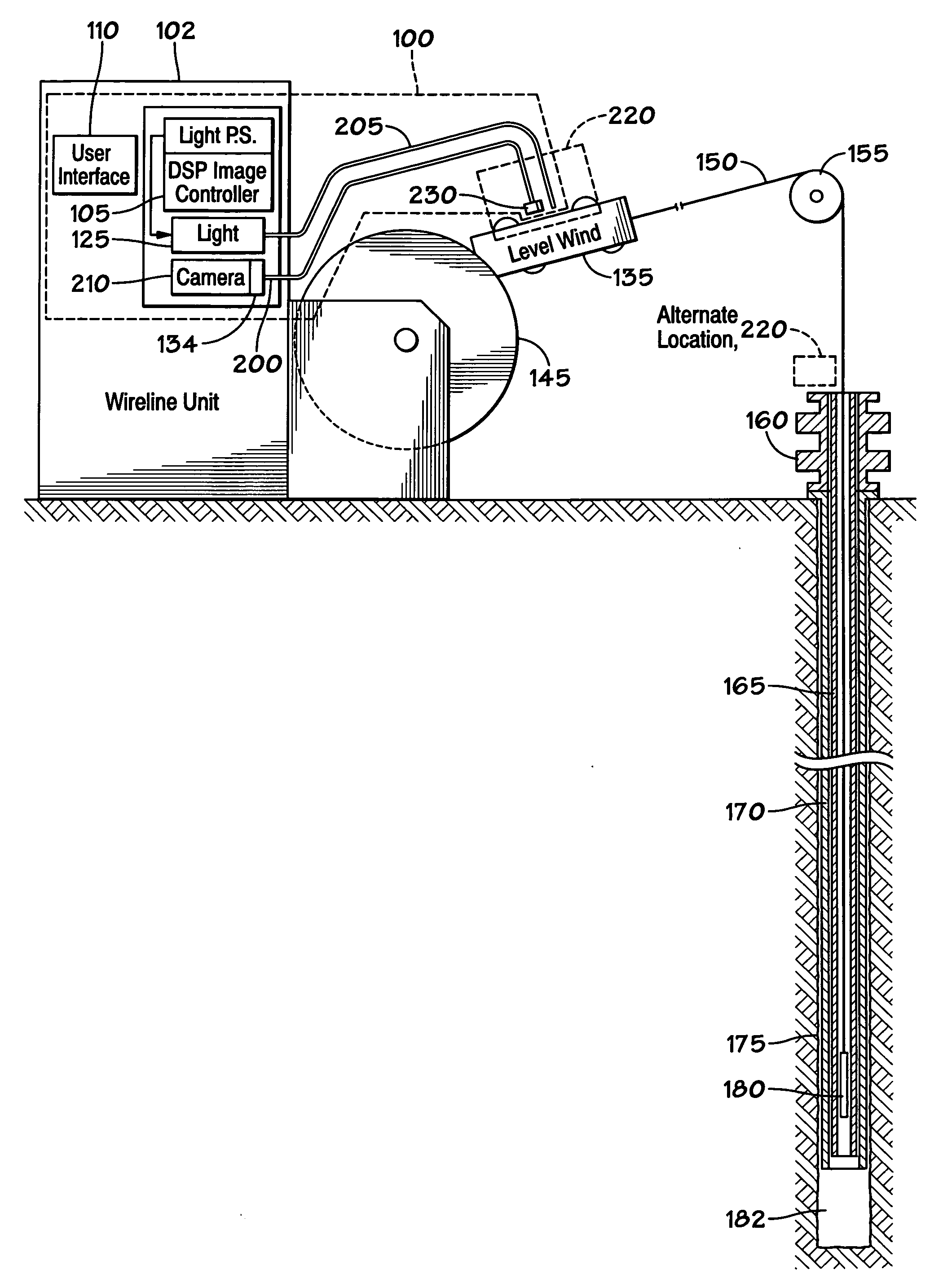
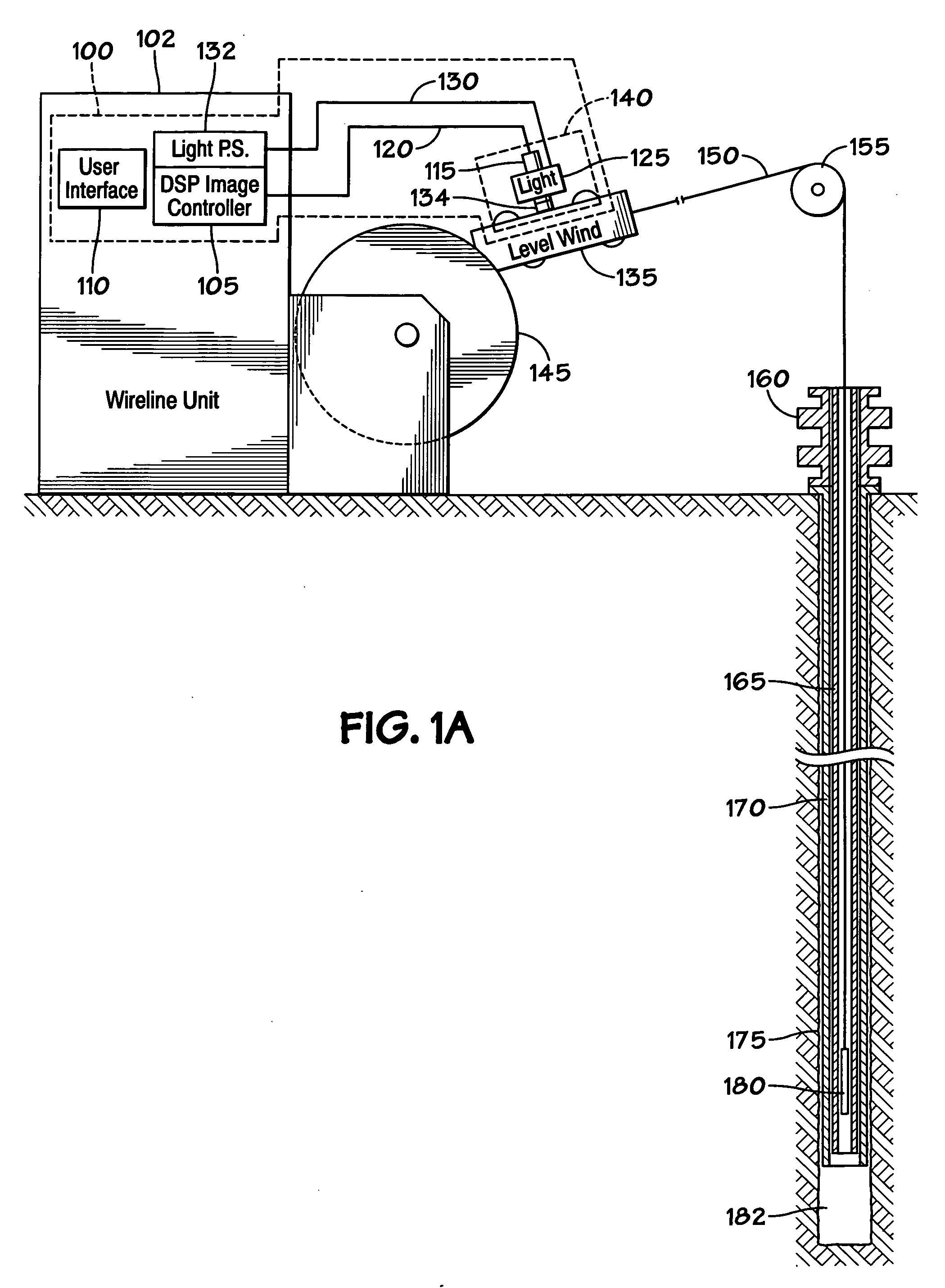
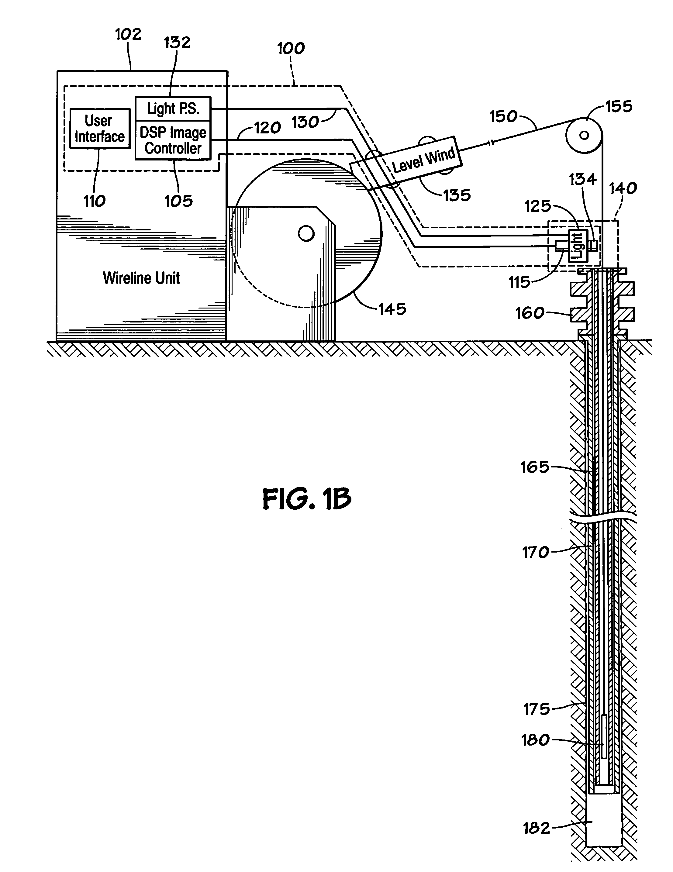
[0052]As shown in FIG. 1A, a non-contact measurement system 100 according to the present invention, includes a digital signal processor image controller 105, a user interface 110, a digital camera 115 with an optically coupled lens system 134 and a power cable and category six ethernet cable 120, and a light source 125 with a power cable 130 and a power source 132 (see FIG. 3A). The digital camera 115, lens system 134, and the light source 125 are mounted at a level wind 135 in a sensor head 140. The level wind 135 is mounted to a wireline drum 145 and a wireline cable 150 passes from the wireline drum 145 through the level wind 135 and past the digital camera 115 and light source 125. The wireline cable 150 passes over a sheave 155 and is inserted into the wellbore tubing 165, through a blowout preventer 160. The lens system 134 is adjacent the path of wireline cable or coiled tubing and is optically coupled to the digital camera 115. The wellbore tubing 165 is inside and coinciden...


PUM


Abstract

A system for measuring at least one parameter of moving cable, the system including a system power source, a digital camera adjacent a moving cable for taking digital images of the cable as the cable moves past the digital camera, the digital camera producing signals corresponding to the digital images, a signal processor for receiving the signals from the digital camera and for processing the images to produce processed image data, the signal processor for calculating measurements of the at least one parameter of the cable based on the processed image data, the system power source for powering systems devices, e.g., the digital camera and/or the signal processor. This abstract is provided to comply with the rules requiring an abstract which will allow a searcher or other reader to quickly ascertain the subject matter of the technical disclosure and is submitted with the understanding that it will not be used to interpret or limit the scope or meaning of the claims, 37 C.F.R. 1.72(b).

Description

BACKGROUND OF THE INVENTION[0001]1. Field of the Invention[0002]The present invention is directed to systems and methods for measurements of wireline cable and coiled tubing as they are used in the oil or gas industry; and, in certain particular aspects, to non-contact measurement (e.g. of depth and velocity) of wireline cable and coiled tubing.[0003]2. Description of Related Art[0004]There are a variety of known methods used to measure the depth of equipment within oil and gas wells. In many instances these methods employ devices that are in physical contact with a conducting mechanism that transports the equipment through the wellbore, e.g. on a wireline cable (“wireline”) or with coiled tubing. For example, often, when a wireline or coiled tubing operation is in progress, one known method of depth measurement relies on either one or two measurement wheels that are in contact with the wireline or coiled tubing that are in turn connected to quadrature encoders. The quadrature encod...

Claims


Application Information

Patent Timeline
IPC IPC(8): H04N7/18H04N5/228
CPCE21B47/04H04N7/185G01P3/806G01P3/68
Inventor PUGH, TREVOR K.C.KELLEHER, PATRICK A.NEWMAN, KENNETH R.
Owner NAT OILWELL VARCO LP
Why Eureka
Try Eureka