Compact apparatus for extracting water from air

a compact apparatus and air technology, applied in water conservation, separation processes, membrane technology, etc., can solve the problems of high energy consumption, low water production, and high energy consumption, and achieve the effect of reducing the number of contaminated water sources

Active Publication Date: 2021-09-16
CZECH TECH UNIV IN PRAGUE
View PDF0 Cites 3 Cited by
  • Summary
  • Abstract
  • Description
  • Claims
  • Application Information

AI Technical Summary

Benefits of technology

[0019]In the embodiment just mentioned, it is advantageous to position a flap for connecting the air ducts in the first air duct in the space between the cooler and the recuperative heat exchanger.

Problems solved by technology

The disadvantage of such a solution is that in the case of low specific humidity of the ambient air below 5 g / kg of dry air, the water production is very low and at the same time energy-intensive.
Therefore, for example, in desert conditions, conventional units for producing water from atmospheric moisture simply by cooling below the dew point do not produce any water.
The disadvantage of the previously known apparatuses of this type is still the relatively high energy consumption.
The heat from the cooling remains unused, and no cold recovery is described, this results in high energy consumption.
The disadvantage is also that the source of electricity for the operation of the unit is electricity supplied from the network.
Therefore, it cannot be an autonomous apparatus.
The main disadvantage is the very small production of water in desert climatic conditions, compared to the proposed apparatus.
The disadvantage of such a apparatus is that it can only operate in cold or humid areas where the temperature of the dehumidified process air is sufficiently below the dew point temperature of the humidified air.
A clear disadvantage of such an apparatus is that for the water vapor to condense, the ambient air temperature needs to be sufficiently below the dew point temperature so that water condenses in the cooler.
The cold from the cooler is used in one of the proposed embodiments, but this is via two liquid exchangers, which is less efficient than using one air recuperative exchanger.
The disadvantage of such an apparatus is also the concept of two air streams, i.e. the operation of two suction devices compared to a single-stream design.
The disadvantage of the solutions known from prior art is therefore the limited scope of use, either in areas with high humidity or with low ambient air temperature.
In the case of dry warm areas such as deserts, some apparatuses exhibit low water production or high demands for the supply of external (non-renewable) energy.
None of these apparatuses are capable to simultaneously meet the requirement for small dimensions of the apparatus allowing mobility and simultaneously the requirement for an autonomous operation not utilizing the supply of external (non-renewable) energy.

Method used


Image

  • Compact apparatus for extracting water from air
  • Compact apparatus for extracting water from air

Examples


Embodiment Construction

[0027]The advantageous embodiments described below illustrate only some of the many possible solutions falling within the protection scope of the invention and illustrate the idea of the invention. These are only selected advantageous embodiments, which in no way limit the scope of protection of the invention.

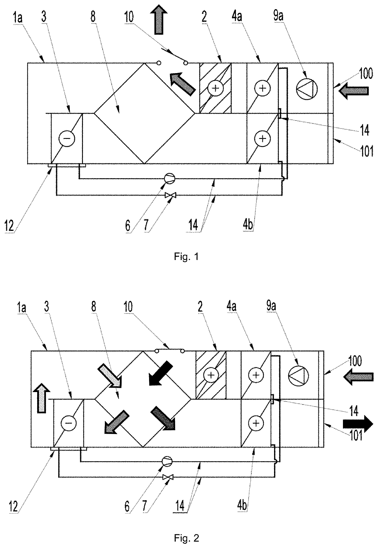
[0028]FIGS. 1 and 2 depict an exemplary embodiment of a compact air water extraction apparatus according to the present invention with one sorption, typically lamellar heat exchanger with an internal source of energy.

[0029]We will first describe the design of the apparatus and then its function in more detail.

[0030]It can be seen that the apparatus comprises a first air duct 1a having a first opening 100 of the first air duct for air intake and / or exhaust and also a second opening 101 of the first air duct for air intake and / or exhaust, whereas in this first air duct 1a are positioned: a cooler 3 and a first suction device 9a for drawing air into the first air duct 1a, and at l...


PUM

PropertyMeasurementUnit
volumeaaaaaaaaaa
temperatureaaaaaaaaaa
specific humidityaaaaaaaaaa

Abstract

The apparatus comprises a first air duct with a first opening and a second opening, in the first air duct are: a cooler, a first suction device and at least part of a sorption heat exchanger having an integrated heating and/or an upstream device for preheating the incoming air. An element for collecting condensed water is also included. The apparatus also comprises a recuperative heat exchanger, which is positioned in the first air duct between the cooler and the sorption exchanger and simultaneously also between the cooler and the second opening. The recuperative heat exchanger has at least two internal conduits connected in such manner, that the first of these internal conduits air-interconnects the sorption exchanger and the cooler and that the second of these internal conduits air-interconnects the cooler and the second opening. The first and second internal conduits of the recuperative heat exchanger are in mutual thermal contact. The sorption exchanger is also air-interconnected to the first opening.

Description

CROSS-REFERENCE TO RELATED APPLICATIONS[0001]This application claims priority to Czech Patent Application No. 2020-126, filed on Mar. 10, 2020, issued as Czech Patent No. 308655 on Dec. 17, 2020, incorporated herein by reference in its entirety.FIELD OF THE INVENTION[0002]The present invention relates to a mobile and in some possible embodiments also autonomous apparatus allowing the production of water from air even in desert climates, in a very small and compact design.BACKGROUND[0003]Several apparatuses are currently available on the market operating on the principle of cooling the ambient air by an exchanger with a temperature lower than the dew point temperature, wherein water vapor from the air condensates on its surface in the form of water droplets. The disadvantage of such a solution is that in the case of low specific humidity of the ambient air below 5 g / kg of dry air, the water production is very low and at the same time energy-intensive. Therefore, for example, in deser...

Claims


Application Information

Patent Timeline
Patent Type & Authority Applications(United States)
IPC IPC(8): B01D5/00E03B3/28
CPCB01D5/0003E03B3/28B01D2257/80B01D5/009B01D5/0075B01D5/0039B01D53/04B01D53/06Y02P70/10B01D3/007Y02A20/00
Inventor POKORNÝ, NIKOLASHEMELIN, VIACHESLAVMATUSKA, TOMÁS
Owner CZECH TECH UNIV IN PRAGUE
Why Eureka
Try Eureka