Device for in vivo delivery of bioactive agents and method of manufacture thereof

Active Publication Date: 2005-08-25
VACTRONIX SCI LLC
View PDF74 Cites 77 Cited by
  • Summary
  • Abstract
  • Description
  • Claims
  • Application Information

AI Technical Summary

Benefits of technology

[0009] The present invention is directed, generally, to an implantable medical device which is deliverable within an anatomical passageway and is capable of restoring and maintaining patency of the anatomical passageway and delivering a bioactive agent within the anatomical passageway. While not limiting the present invention, a common use for the present invention is as a coronary or other vascular stent device which is percutanteously delivered to a situs within the body's vascular system using catheter-based approaches and, once implanted at the desired situs, is capable of releasing a bioactive agent to facilitate and promote a healing response within damaged or injured regions of the vasculature.
[0024] In another particular form the invention, the sensor comprises a plurality of cantilever members positioned on at least one of the proximal, distal or intermediate regions of the endoluminal device and positioned on at least one of the luminal or abluminal wall surfaces of the endoluminal device. To facilitate ease of detection, a plurality of groups of cantilever members are provided, each group is formed of a plurality of individual cantilever members, with each individual cantilever members in the group having identical transition temperatures. The plurality of groups of cantilever members are arrayed along the longitudinal axis of the endoluminal device in such a manner as to create a continuum of groups of cantilever members having different stress-strain transition pressures. Changes in applied stress or strain, such as blood pressure or blood flow shear stress, at the site of the endoluminal device are indicated by the stress and strain acting on the cantilever members or groups of cantilever members which provides a corresponding frequency shift in energy reflected, when compared to a baseline stress-strain for unloaded cantilever members. The position and frequency shift of the cantilever members may be determined by radiography, ultrasonography, magnetic resonance imaging or other means which provides a detectable image of the position of the individual cantilever members and groups of cantilever members or is capable of measuring frequency shifts due to differential stress-strain loading onto the cantilever members.
[0027] Because of their use as a structural scaffold and the requirement that stents be delivered using transcatheter approaches, stents necessarily are delivered in a reduced diametric state and are expanded or allowed to expand in vivo to an enlarged diametric state. Thus, all stents have certain structural regions that are subject to higher stress and strain conditions than other structural regions of the stent. Thus, it may be advantageous to position the internal cavities that retain the bioactive agents in structural regions of the stent that are subjected to relatively lower stress and strain during endoluminal delivery and deployment. Alternatively, where delivery of a bolus of a bioactive agent is desired, internal cavities may be positioned in regions that undergo large deformation during delivery and deployment thereby forcing the bioactive agent out of the internal cavity under the positive pressure exerted by the deformation. Diffusion forces, then, elute remaining bioactive agent present in either the region of large deformation or the regions of lower stress and strain.

Problems solved by technology

However, the restenosis rate of approximately forty percent is unacceptably high.
While the use of endoluminal stents has successfully decreased the rate of restenosis in angioplasty patients, it has been found that a significant restenosis rate continues to exist even with the use of endoluminal stents.
Where biodegradable or non-biodegradable polymer-based or polymer-coated stents have been used, the polymers cause an immune inflammatory response once the drug is eluted out of the polymer.

Method used


Image

  • Device for in vivo delivery of bioactive agents and method of manufacture thereof
  • Device for in vivo delivery of bioactive agents and method of manufacture thereof
  • Device for in vivo delivery of bioactive agents and method of manufacture thereof

Examples


Embodiment Construction

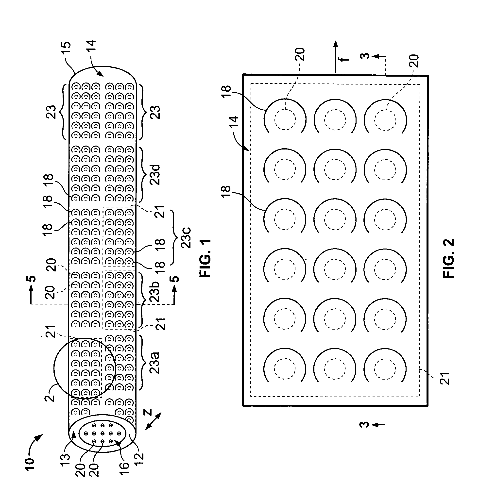
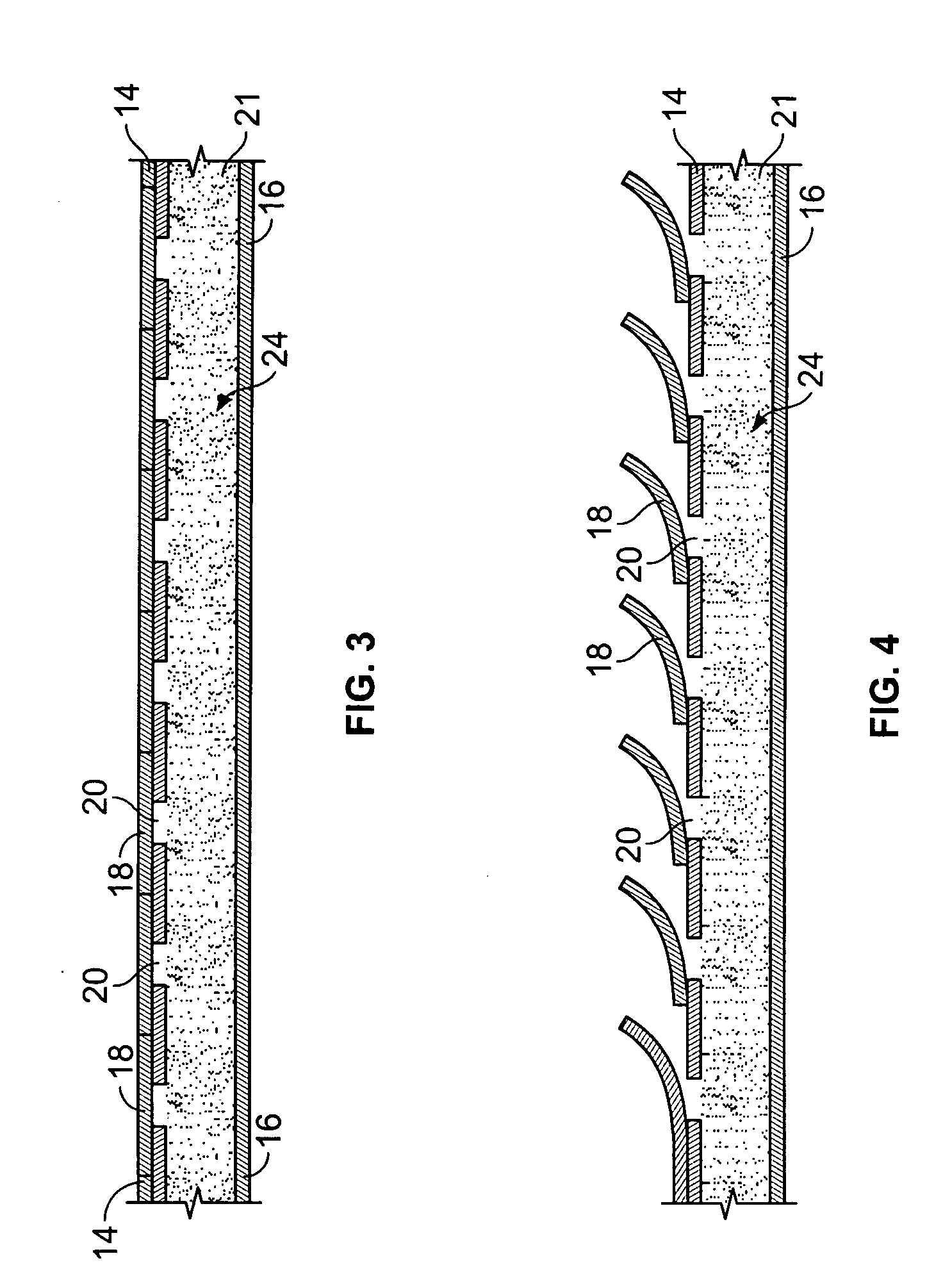
[0037] With particular reference to FIGS. 1 and 2, the drug-eluting device 10 of the present invention consists generally of a body element 12, which for purposes of illustration only, is depicted in a generally tubular conformation having a first wall surface 14 and a second wall surface 16, a first end surface 13 and an opposing second end surface 15. A plurality of openings 20 pass through either or both of the first wall surface 14 and the second wall surface 16 and communicate between at least one chamber 21, shown in phantom, which resides entirely within the z-axis thickness of the drug-eluting device 10 and is defined between the first wall surface 14 and the second wall surface 16 with only at least one of the plurality of openings 20 communicating between the internal chamber 21 and either the first 14 or second 16 wall surface of the drug-eluting device 10. A plurality of cover members 18 are provided in or in association with either or both of the first wall surface 14 a...


PUM


Abstract

The present invention consists of an implantable structural element for in vivo controlled delivery of bioactive active agents to a situs in a body. The implantable structural element may be configured as an implantable prosthesis, such as an endoluminal stent, cardiac valve, osteal implant or the like, which serves a dual function of being prosthetic and a carrier for a bioactive agent. Control over elution of the bioactive agents occurs through a plurality of cantilever-like cover members which prevent drug elution until an endogenous or exogenous stimulus causes the cover members to open and permit drug elution.

Description

CROSS REFERENCE TO RELATED INVENTIONS [0001] This is a continuation-in-part of commonly assigned and co-pending U.S. patent applications Ser. Nos. 09 / 783,633 filed Feb. 14, 2001, 09 / 716,146 filed Nov. 17, 2000 and 10 / 258,087 filed Oct. 17, 2002 as a continuation-in-part of Ser. No. 09 / 716,146 filed Nov. 17, 2000.BACKGROUND OF THE INVENTION [0002] The present invention relates generally to an implantable device for supporting a lumenal passageway and, also, delivering, in vivo, bioactive compounds. More particularly, the present invention relates to an implantable device equipped with cantilever controls for automated delivery of bioactive compounds in response to a predetermined physiological event. [0003] Occlusive diseases, disorders or trauma cause patent body lumens to narrow and restrict the flow or passage of fluid or materials through the body lumen. One example of occlusive disease is arteriosclerosis in which portions of blood vessels become occluded by the gradual build-up...

Claims


Application Information

Patent Timeline
IPC IPC(8): A61B5/00A61B5/0215A61B5/07A61F2/00A61F2/82A61F2/86A61L27/04A61L27/54A61L31/02A61L31/16
CPCA61B5/01A61F2210/0076A61B5/021A61B5/0215A61B5/026A61B5/076A61B5/4839A61B5/6862A61B5/6876A61F2/07A61F2/82A61F2/86A61F2/91A61F2/915A61F2002/91533A61F2002/91541A61F2002/91558A61F2250/0001A61F2250/0067A61F2250/0068A61L27/04A61L27/54A61L31/022A61L31/16A61L2300/602A61B5/02055A61F2240/001
Inventor BOYLE, CHRISTOPHER T.BAILEY, STEVEN R.MARTON, DENESBANAS, CHRISTOPHER E.
Owner VACTRONIX SCI LLC
Why Eureka
Try Eureka