Measurement apparatus, lithography apparatus and article manufacturing method

a technology of lithography and measurement apparatus, applied in the direction of photomechanical apparatus, instruments, image enhancement, etc., can solve the problems of productivity degradation and measurement accuracy declin

Active Publication Date: 2022-08-04
CANON KK
View PDF11 Cites 0 Cited by
  • Summary
  • Abstract
  • Description
  • Claims
  • Application Information

AI Technical Summary

Benefits of technology

[0008]The present invention provides a measurement apparatus advantageous in measuring the position of a pattern provided in a target object.

Problems solved by technology

However, the related art has a problem that when the intensity of detection light varies between the patterns in the same layer or different layers due to a difference in reflectance in the substrate, the productivity may be degraded due to a decrease in measurement accuracy or a measurement error.

Method used


Image

  • Measurement apparatus, lithography apparatus and article manufacturing method
  • Measurement apparatus, lithography apparatus and article manufacturing method
  • Measurement apparatus, lithography apparatus and article manufacturing method

Examples


first embodiment

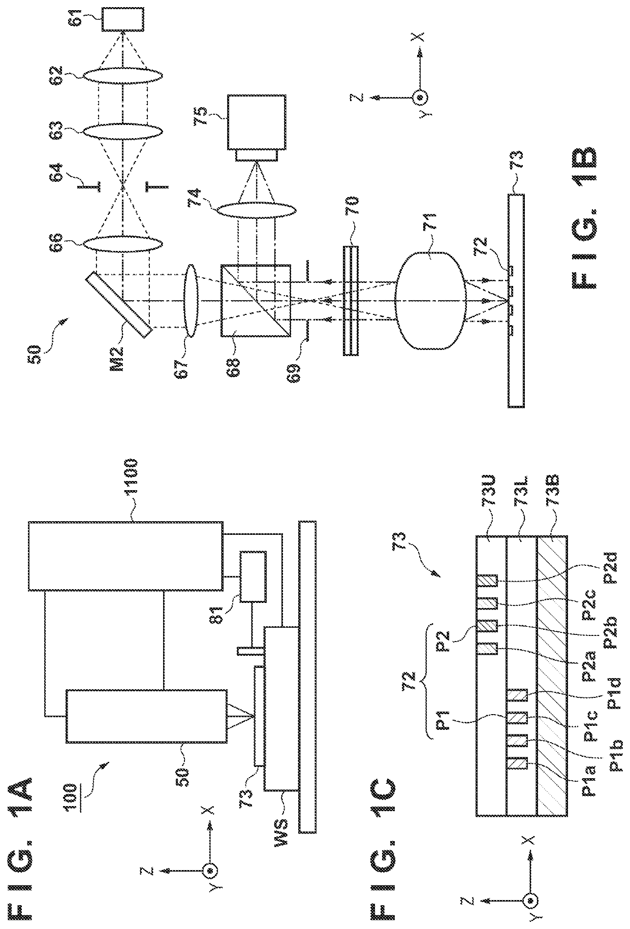
[0022]FIG. 1A is a schematic view showing the arrangement of a measurement apparatus 100 as one aspect of the present invention. The measurement apparatus 100 is an overlay measurement apparatus (overlay inspection apparatus) that measures an overlay error in a substrate 73, more specifically, relative positions of a plurality of patterns provided in different layers on the substrate (on the target object). As shown in FIG. 1A, the measurement apparatus 100 includes a substrate stage WS which holds the substrate 73, a measurement unit 50, and a control unit 1100.

[0023]The substrate 73 is the target object whose overlay error is measured by the measurement apparatus 100. The substrate 73 is, for example, a substrate used to manufacture a device such as a semiconductor device or a liquid crystal display device and, more specifically, includes a wafer, a liquid crystal substrate, another processing target substrate, or the like.

[0024]The substrate stage WS holds the substrate 73 via a ...

second embodiment

[0070]FIG. 7A is a schematic view showing the arrangement of an exposure apparatus EXA. The exposure apparatus EXA is a lithography apparatus which is used in a lithography process as a manufacturing process of a device such as a semiconductor device or a liquid crystal display device and forms a pattern on a substrate 83. The exposure apparatus EXA exposes the substrate 83 via a reticle 31 serving as an original, thereby transferring the pattern of the reticle 31 to the substrate 83. In this embodiment, the exposure apparatus EXA employs a step-and-scan method, but it can also employ a step-and-repeat method or other exposure methods.

[0071]As shown in FIG. 7A, the exposure apparatus EXA includes an illumination optical system 801, a reticle stage RS which holds the reticle 31, a projection optical system 32, a substrate stage WS which holds the substrate 83, a position measurement apparatus 200, and a control unit 1200.

[0072]The illumination optical system 801 is an optical system ...

third embodiment

[0100]With reference to FIGS. 10A, 10B, and 10C, a position measurement apparatus in the third embodiment will be described. The position measurement apparatus has an arrangement similar to that of the position measurement apparatus 200 shown in FIG. 7B, so that a detailed description thereof will be omitted here. The position measurement apparatus in this embodiment is different from the position measurement apparatus 200 in that it measures not the position of a mark provided in one layer on a substrate (on a target object) but the position of a mark formed by a plurality of patterns provided in different layers on the substrate.

[0101]FIG. 10A is a view showing an example of the arrangement of a mark 92 provided in a substrate 93 serving as a measurement target object of the position measurement apparatus. In this embodiment, the substrate 93 is a substrate formed by three layers of a lowermost layer 93B, a first layer 93L, and a second layer 93U. The mark 92 is formed by a first ...


PUM

PropertyMeasurementUnit
widthaaaaaaaaaa
speedaaaaaaaaaa
reflectanceaaaaaaaaaa

Abstract

The present invention provides a measurement apparatus for measuring a position of a first pattern and a position of a second pattern provided in a target object, the apparatus including an image capturing unit including a plurality of pixels which detect light from the first pattern and light from the second pattern, and configured to form an image capturing region used to capture the first pattern and the second pattern by the plurality of pixels, and a control unit configured to adjust the image capturing unit such that a relative ratio of an intensity of a detection signal of the first pattern generated based on an output from a first image capturing region and an intensity of a detection signal of the second pattern generated based on an output from a second image capturing region falls within an allowable range.

Description

BACKGROUND OF THE INVENTIONField of the Invention[0001]The present invention relates to a measurement apparatus, a lithography apparatus and an article manufacturing method.Description of the Related Art[0002]In recent years, due to high integration and miniaturization of semiconductor integrated circuits, the line width of a pattern to be formed on a substrate has become extremely small. Therefore, further miniaturization is required in a lithography process of forming the pattern (resist pattern) on the substrate. In a step-and-repeat type exposure apparatus or a step-and-scan type exposure apparatus which is used in the lithography process, a pattern is formed on a substrate by imaging the light (exposure light) from an original at a predetermined position on the substrate through a projection optical system. Accordingly, in order to meet the demand for pattern miniaturization, it is important to align the relative positions of the original and the substrate with high accuracy. F...

Claims


Application Information

Patent Timeline
Patent Type & Authority Applications(United States)
IPC IPC(8): G03F9/00G03F7/20G06T7/00
CPCG03F9/7088G03F7/70633G06T2207/30148G03F9/7076G06T7/0004G03F7/70683G03F9/7003G03F9/7049G03F7/70616G03F9/7092G03F9/7046G01B11/03G01B11/026G01B11/25
Inventor YAMAGUCHI, WATARU
Owner CANON KK
Why Eureka
Try Eureka