Image sensing apparatus and control method therefor, and image processing apparatus and reduction method

a technology of image processing apparatus and control method, which is applied in the direction of color television details, television system details, television system, etc., can solve the problems of difficult prevention, disadvantageous in being visually noticeable, and above-described crosstalk noise due to vertical transfer pulses, so as to reduce the influence of crosstalk noise and reduce the frame rate in shooting

Inactive Publication Date: 2013-10-15
CANON KK
View PDF9 Cites 0 Cited by
  • Summary
  • Abstract
  • Description
  • Claims
  • Application Information

AI Technical Summary

Benefits of technology

[0022]The present invention has been made in consideration of the above situation, and is provided to reduce the influence of crosstalk noise in image signals obtained by shooting, without lowering the frame rate in shooting.

Problems solved by technology

However, this driving method has the problem of crosstalk noise being superimposed on signals of pixels in an effective area (hereinafter, referred to as “effective pixel signals”) read out from the horizontal transfer registers, at the timings of rising and dropping driving pulses for vertical transfer (vertical transfer pulses).
It is difficult to prevent the above-described crosstalk noise due to the vertical transfer pulses from being superimposed, because the noise leaks into the effective pixel signals through various transmission paths, such as a path between substrates or between signal electrodes inside an image sensor.
Furthermore, the above-described crosstalk noise due to the vertical transfer pulses is disadvantageous in being also more likely to be visually noticeable as image noise, because the crosstalk noise will be vertical noise superimposed on effective pixel signals in the same column positions for each horizontal line.
However, every time the transfer operation by the VCCD 2 is carried out during the horizontal effective operation period, crosstalk noise will be generated inside the CCDs at the timings of rising and dropping each of the vertical transfer pulses V1, V2, V3, V4 applied to the VCCD 2, thereby resulting in the crosstalk noise superimposed on image sensing voltage signals (CCD outputs) eventually read out from the output amplifier 4.
Therefore, in a case in which the sensitivity is set higher in the image sensing apparatus, that is, in a case in which the amplification of the gain amplifier is larger, the crosstalk noise will become recognizable and more likely to be noticeable.
However, while the technique disclosed in Japanese Patent No. 3715781 is effective in a case in which reading from a portion of an effective pixel area is carried out, such as in photometric operation and electronic zoom operation, speeding up is not possible in the operation of reading out normal still images or moving images.
Furthermore, the technique described in Japanese Patent Laid-Open No. 2005-269060 fails to completely eliminate the influence of the crosstalk noise superimposed on the effective pixel signals, thereby producing residual noise components.
This becomes a factor hindering increase in the sensitivity of the image sensing apparatus.

Method used


Image

  • Image sensing apparatus and control method therefor, and image processing apparatus and reduction method
  • Image sensing apparatus and control method therefor, and image processing apparatus and reduction method
  • Image sensing apparatus and control method therefor, and image processing apparatus and reduction method

Examples


first embodiment

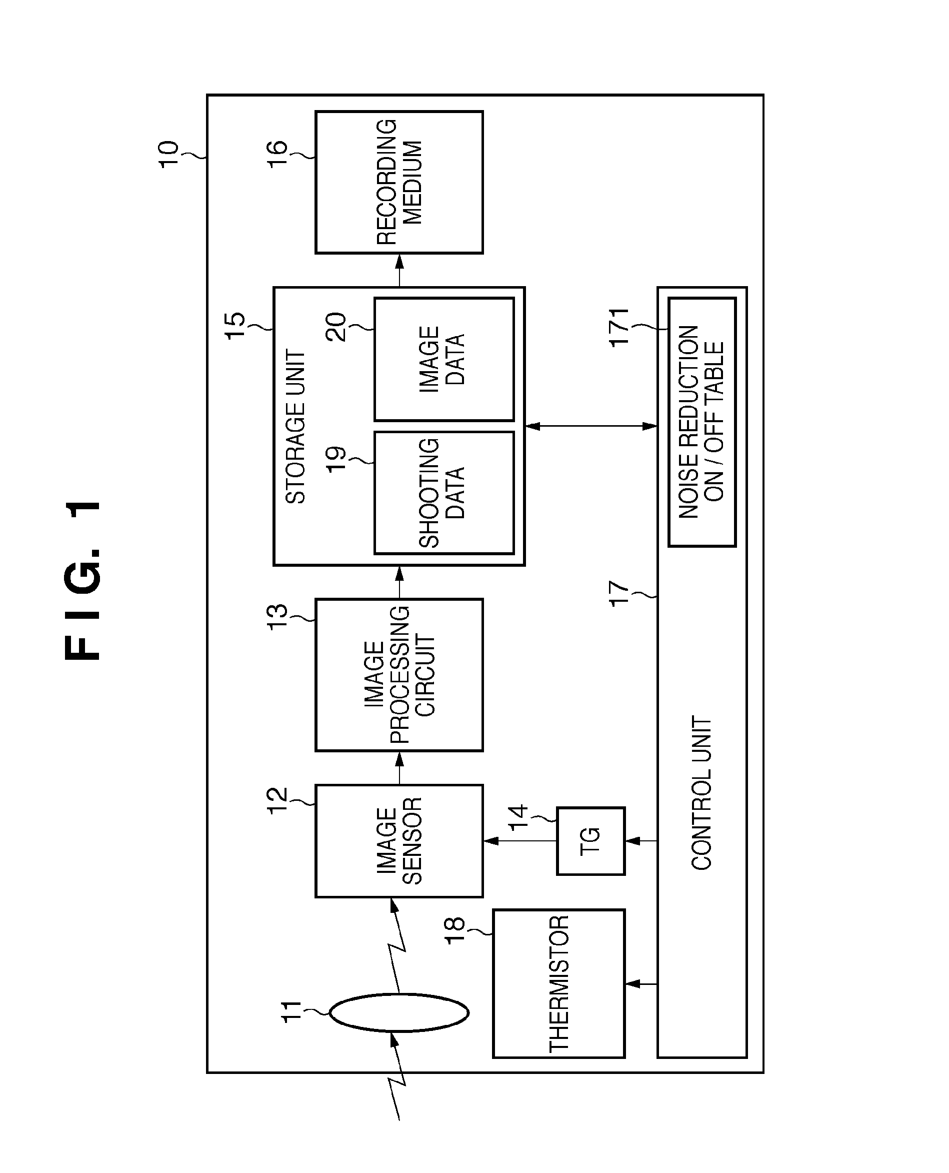
[0036]FIG. 1 is a block diagram illustrating a schematic configuration of an image sensing apparatus 10 according to a first embodiment of the present invention.

[0037]In FIG. 1, reference numeral 12 denotes an image sensor composed of CCDs or the like, which has photoelectric conversion elements for converting incident light into electric signals, and the image sensor 12 has essentially the same configuration as that shown in FIG. 8. More specifically, the image sensor 12 has the vertical CCDs 2, which are multiple vertical transfer registers for transferring signal charges of the PDs 1 in the vertical direction (column direction), and the horizontal CCDs 3 for transferring the signal charge for each line, which has been transferred from the VCCD, in the horizontal direction (row direction). The image sensor 12 has a dummy pixel unit from which signals are read out with no connection to the photoelectric conversion elements, an OB unit that is a pixel unit optically shielded from li...

second embodiment

[0063]Next, a second embodiment of the present invention will be described.

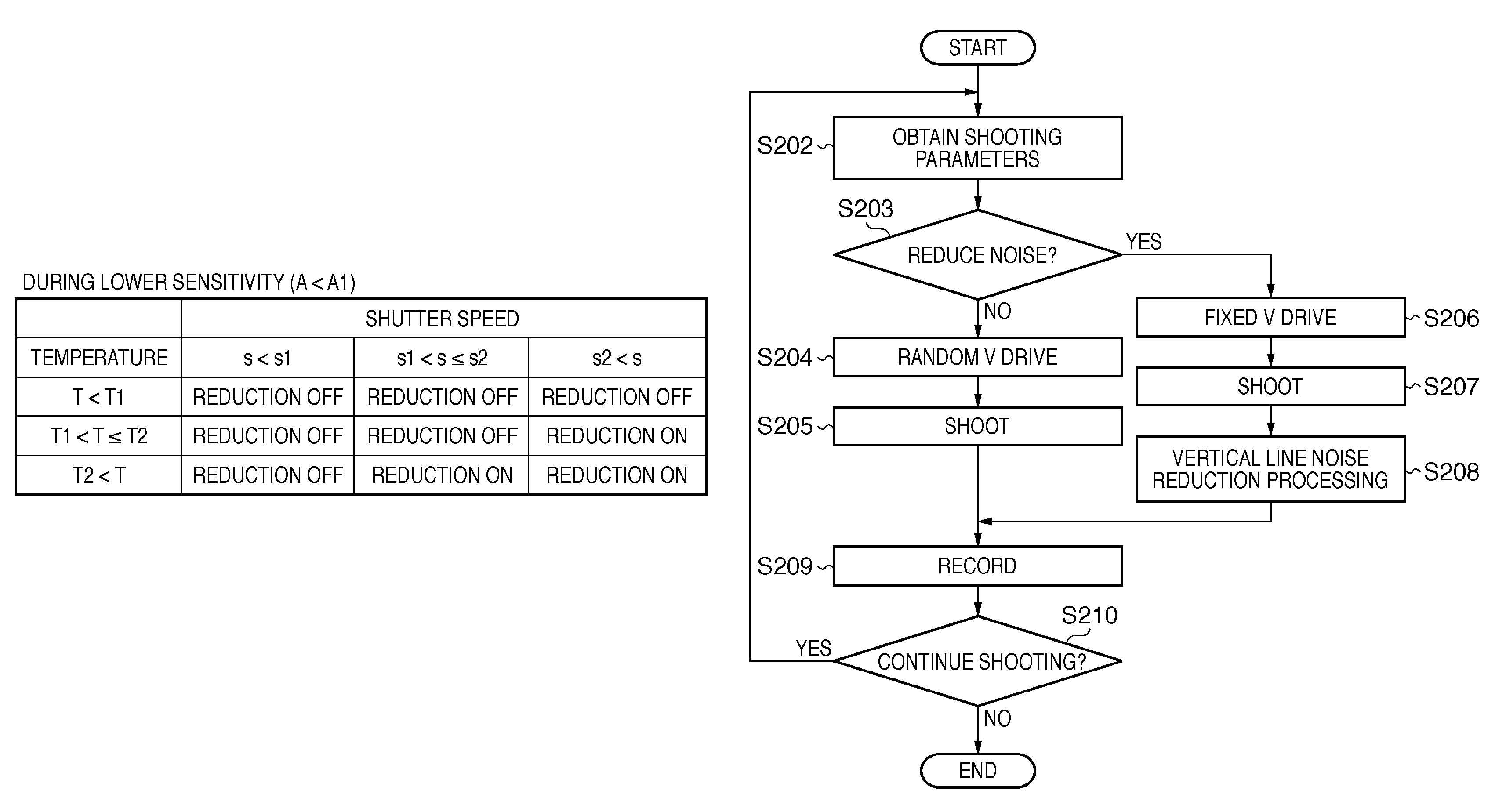
[0064]The vertical line noise reduction described in the first embodiment described above, by subtracting the average values for each column of image signals in the OB unit 402, becomes a factor causing degradation of the S / N ratio. Therefore, the vertical line noise reduction is not carried out under lower sensitivity conditions where vertical line noise is less noticeable.

[0065]However, recently, higher definition image sensors and following more microscopic pixels have progressively developed, decreasing the element sensitivity. Therefore, there are many cases where the amplification of a gain amplifier has to be set high to some extent even under such lower sensitivity conditions.

[0066]The second embodiment is characterized in that vertical transfer pulses are applied to the vertical transfer register such that vertical line noise is rendered less noticeable without decrease of the through rate or degrada...


PUM


Abstract

An image sensing apparatus has an image sensor including two-dimensionally arranged photoelectric conversion elements, a VCCD for transferring in a vertical direction electric charge accumulated in the photoelectric conversion elements, and a HCCD for transferring in a horizontal direction the electric charge transferred from the VCCD, the image sensor for carrying out transfer of electric charge by the VCCD during transfer of electric charge by the HCCD; a noise reduction unit for reducing noise including noise caused by driving the VCCD from an image signal output from the HCCD; and a control unit for controlling whether or not noise reduction is to be carried out based on at least one of the sensitivity, shutter speed, and temperature of the image sensor.

Description

BACKGROUND OF THE INVENTION[0001]1. Field of the Invention[0002]The present invention relates to an image sensing apparatus and a control method therefor, and to an image processing apparatus and a noise reduction method, and more particularly, to an image sensing apparatus for reducing noise caused by driving an image sensor, and a control method therefor, and to an image processing apparatus and a noise reduction method.[0003]2. Description of the Related Art[0004]Recently, image sensing apparatuses such as digital cameras have been actively developed that record and play back images sensed by solid-state image sensors such as CCDs, with the use of, as a recording medium, a memory card including a solid-state memory element, and have become widespread. Behind such wide diffusion lies the spread of personal computers (PCs) that are able to input and process images shot with a digital camera, increased demand for digital image information through the utilization of the Internet or t...

Claims


Application Information

Patent Timeline
Patent Type & Authority Patents(United States)
IPC IPC(8): H04N3/14H04N5/335H04N5/232H04N5/341H04N5/357H04N5/359H04N5/369H04N5/372
CPCH04N5/372H04N25/71
Inventor ISE, MAKOTO
Owner CANON KK
Why Eureka
Try Eureka