
Thin flip chip package structure

a chip and package technology, applied in the direction of semiconductor devices, semiconductor/solid-state device details, electrical devices, etc., can solve problems such as connection with substrates, and achieve the effect of shortening processing time and coupling strength

Active Publication Date: 2013-07-30
CHIPBOND TECH
View PDF3 Cites 2 Cited by
  • Summary
  • Abstract
  • Description
  • Claims
  • Application Information

AI Technical Summary

Benefits of technology

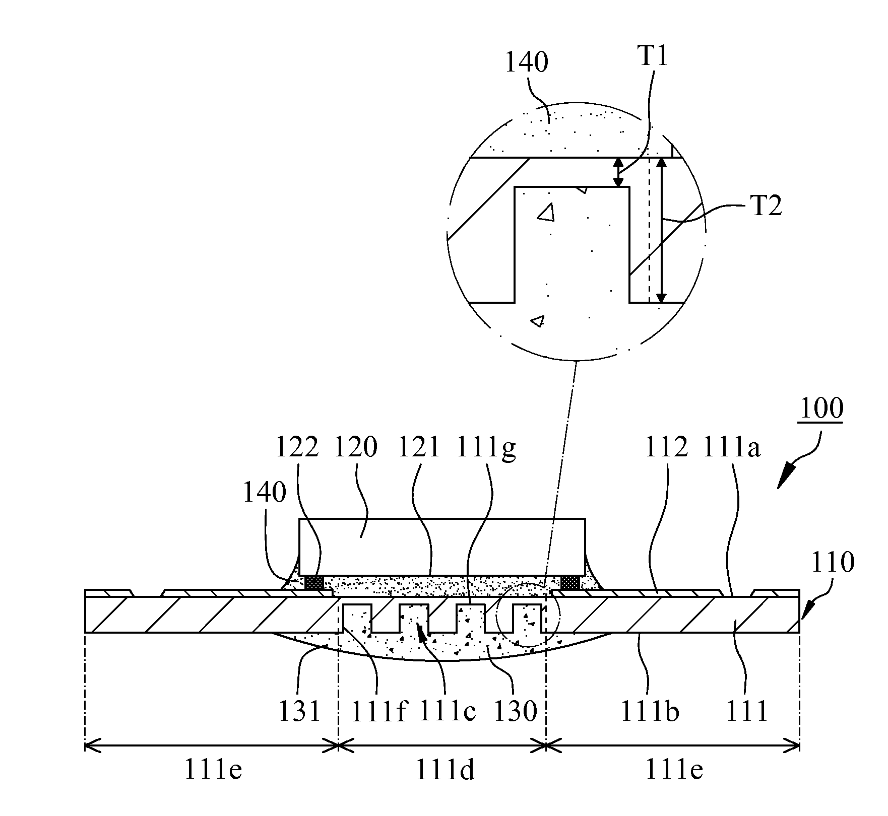
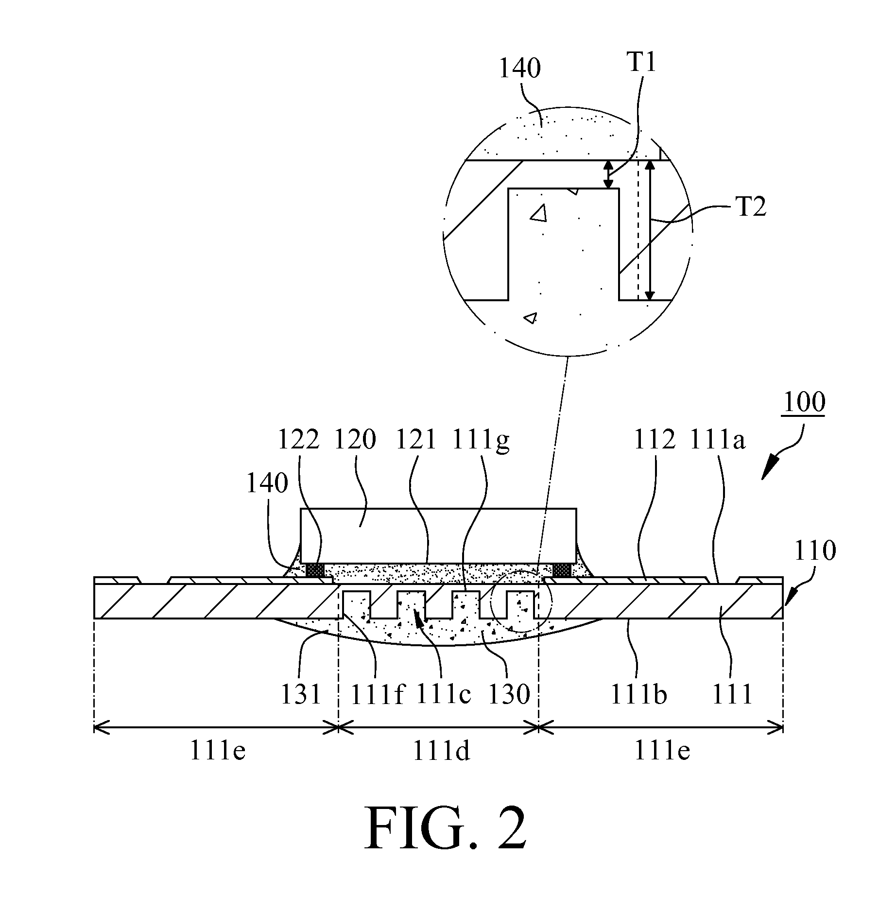
The present invention provides a thin flip chip package structure comprising a substrate, chip, and heat dissipation paste. The substrate has insulating layers with apertures filled with heat dissipation paste and in contact with the chip. The chip is connected to the insulating layer through bumps. This design increases the coupling strength between the heat dissipation paste and the insulating layer. It also eliminates the need for a dam to block sealing resin and has cost- saving and shorter processing duration functions.

Problems solved by technology

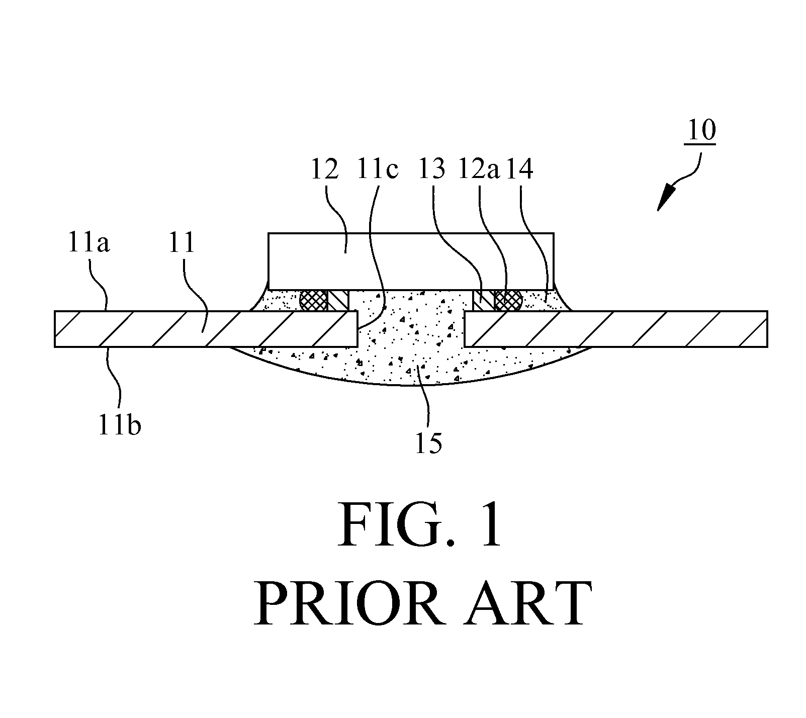
However, an overhigh dam 13 makes the bumps 12a of the chip 12 difficult to connect with the substrate 11 smoothly.

Method used


Image

  • Thin flip chip package structure
  • Thin flip chip package structure
  • Thin flip chip package structure

Examples


Embodiment Construction

[0009]With reference to FIG. 2, a thin flip chip package structure 100 in accordance with a preferred embodiment of the present invention comprises a substrate 110, a chip 120, a heat dissipation paste 130 and a sealing resin 140. The substrate 110 comprises an insulating layer 111 and a trace layer 112, the insulating layer 111 comprises a top surface 111a, a bottom surface 111b and a plurality of apertures 111c formed at the bottom surface 111b, wherein the bottom surface 111b of the insulating layer 111 comprises a disposing area 111d and a non-disposing area 111e. Each of the apertures 111c is located at the disposing area 111d and comprises a lateral wall 111f and a base surface 111g in connection with the lateral wall 111f. A first thickness T1 is formed between the base surface 111g of each of the apertures 111c and the top surface 111a of the insulating layer 111, a second thickness T2 is formed between the top surface 111a and the bottom surface 111b of the insulating layer...


PUM


Abstract

A thin flip chip package structure comprises a substrate, a chip and a heat dissipation paste, the substrate comprises an insulating layer and a trace layer. The insulating layer comprises a top surface, a bottom surface and a plurality of apertures formed at the bottom surface, wherein the bottom surface of the insulating layer comprises a disposing area and a non-disposing area. Each of the apertures is located at the disposing area and comprises a lateral wall and a base surface. A first thickness is formed between the base surface and the insulating layer, a second thickness is formed between the top surface and the bottom surface, and the second thickness is larger than the first thickness. The chip disposed on the top surface comprises a chip surface and a plurality of bumps. The heat dissipation paste at least fills the apertures and contacts the base surface.

Description

CROSS REFERENCE TO RELATED APPLICATIONS[0001]This application claims priority under 35 U.S.C. §119, to Taiwanese Application Number 099218883 filed in Taiwan, R.O.C. on Mar. 9, 2010 and is related to copending U.S. application Ser. No. 13 / 163,877, filed on Jun. 20, 2011.FIELD OF THE INVENTION[0002]The present invention is generally relating to a thin flip chip package structure, more particularly to a thin flip chip package structure with heat dissipation capability.BACKGROUND OF THE INVENTION[0003]With reference to FIG. 1, a conventional thin flip chip package structure 10 comprises a substrate 11, a chip 12, a dam 13, a sealing resin 14 and a heat dissipation paste 15. The substrate 11 comprises a top surface 11a, a bottom surface 11b, and a through hole 11c penetrating the top surface 11a and the bottom surface 11b. The chip 12 disposed on the top surface 11a of the substrate 11 is electrically connected with the substrate 11 and comprises a plurality of bumps 12a. The dam 13 is ...

Claims


Application Information

Patent Timeline
Patent Type & Authority Patents(United States)
IPC IPC(8): H01L23/58
CPCH01L23/3677H01L23/42H01L24/16H01L24/73H01L24/92H01L2224/81191H01L2224/73204H01L2224/92125H01L2924/15159H01L2224/16225H01L2224/16227H01L2924/00014H01L2224/0401
Inventor HSIEH, CHIN-TANGKUO, HOU-CHANGTZOU, DUENG-SHIUTU, CHIA-JUNGSHEU, GWO-SHYAN
Owner CHIPBOND TECH
Learn More