

Secondary battery pack
a secondary battery and battery pack technology, applied in secondary cell servicing/maintenance, batteries, cell components, etc., can solve the problems of lithium secondary battery being heated or exploded, lithium secondary battery having low safety, and many combustibles
- Summary
- Abstract
- Description
- Claims
- Application Information
AI Technical Summary
Benefits of technology
Problems solved by technology
Method used
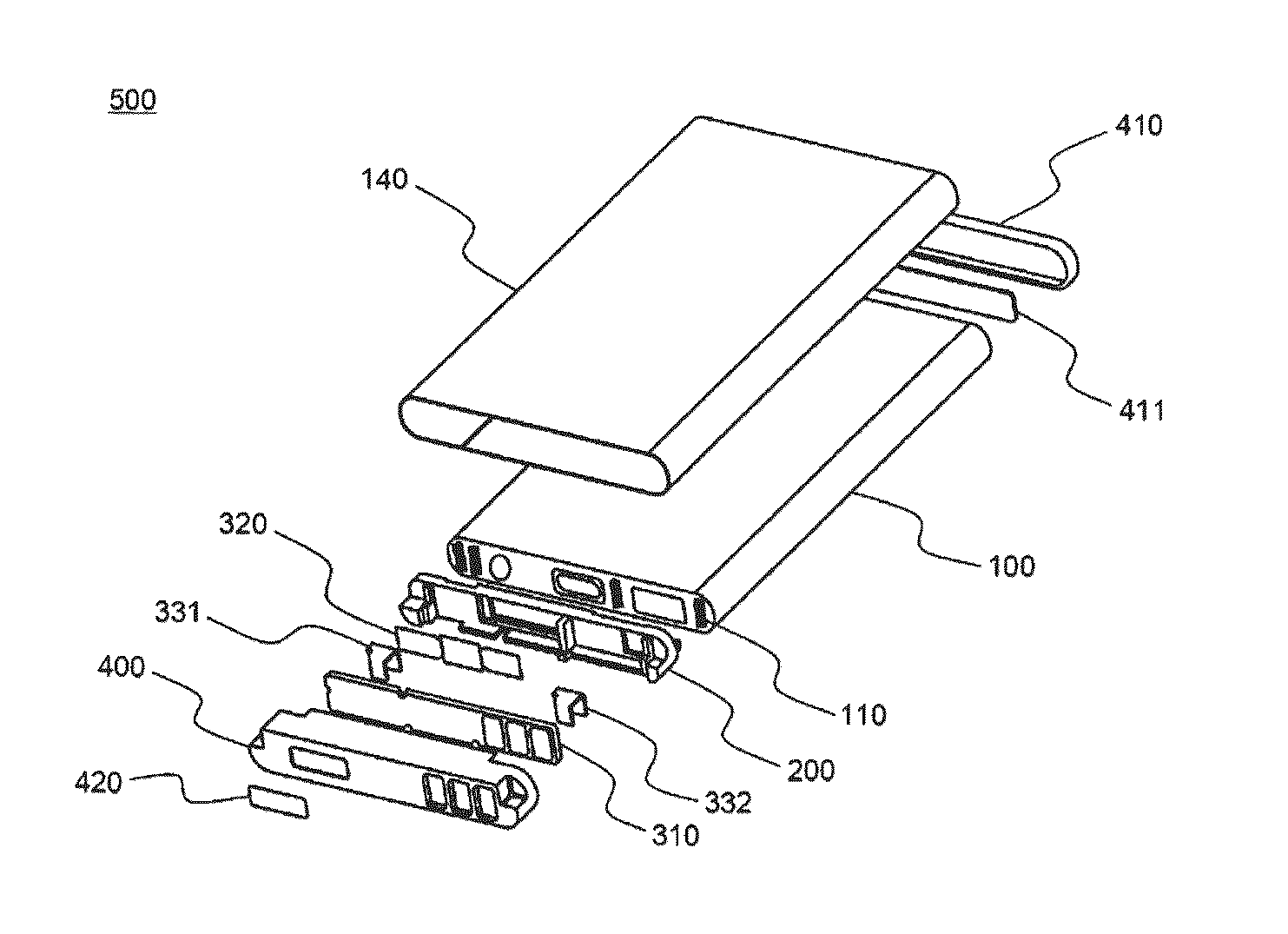
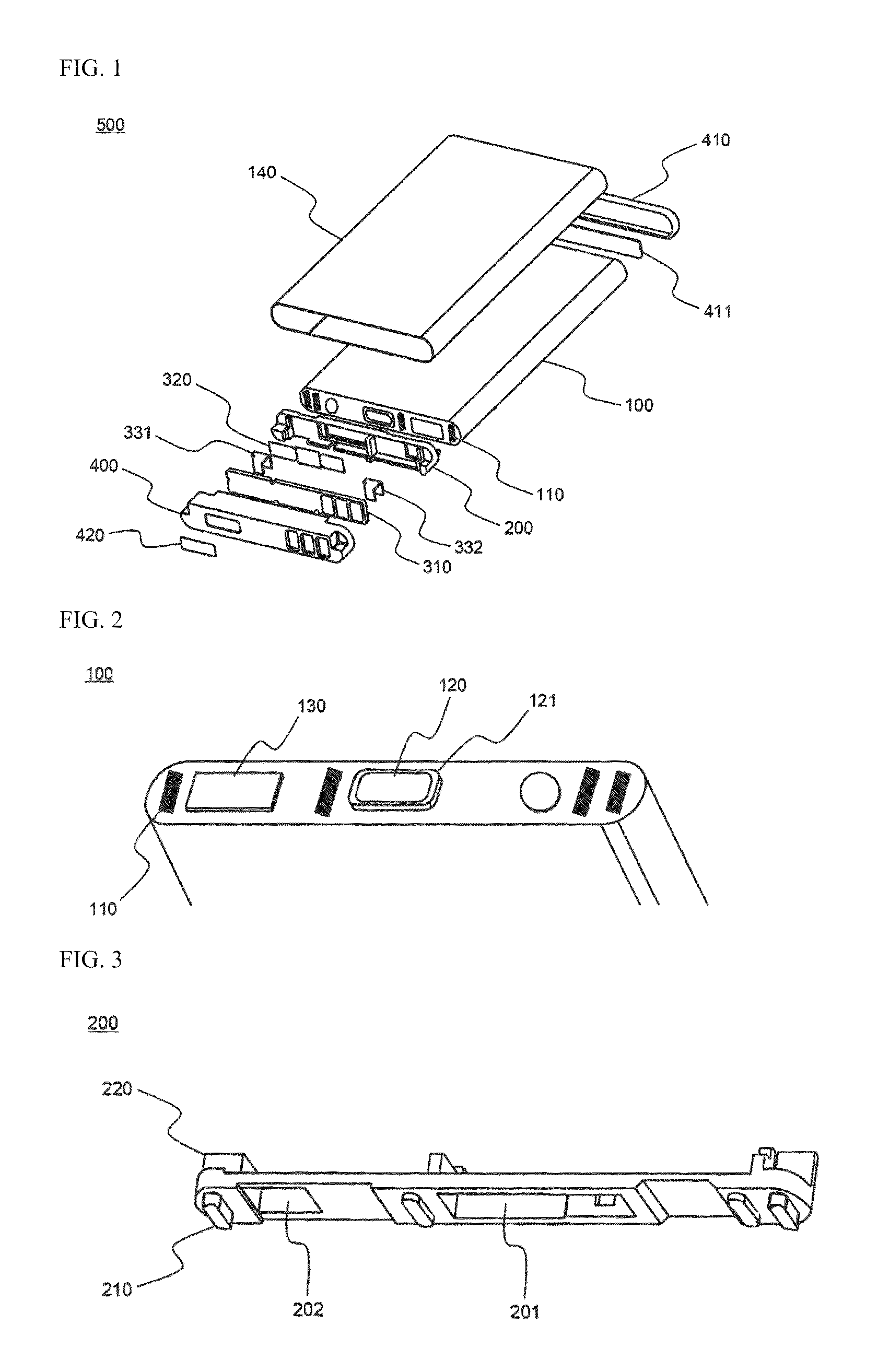
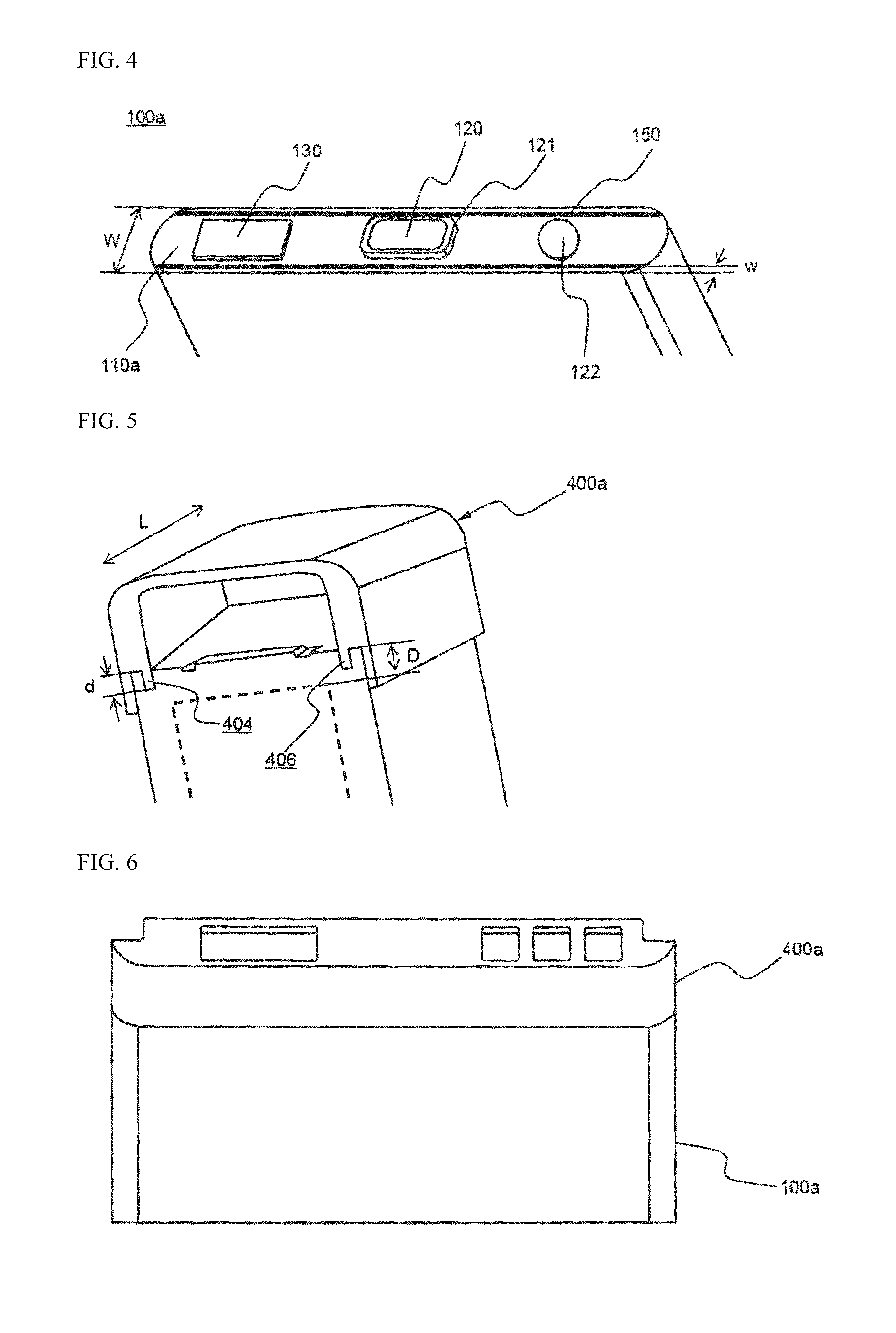
Image

Examples
experimental example 1
[0088]Bending tests were carried out on 20 battery packs manufactured according to Example 1 and 20 battery packs manufactured according to Comparative Example 1 to measure the coupling strength between the battery cell of each of the battery packs and the insulative cap coupled to the battery cell (See FIG. 11). That is, load applied to the middle of each of the battery packs was gradually increased in a state in which the insulative top cap and the insulative bottom cap of each of the battery packs were fixed to measure the magnitudes of the load when the battery packs broke. The experiment results are indicated in Table 1 below.
[0089]
TABLE 1Breaking load (kgf)Example 1Comparative Example 125 or less0625 to 3001230 to 350245 to 500—50 to 5512—55 or more8—
[0090]As can be seen from Table 1 above, the coupling force of the battery packs manufactured according to the example of the present invention was greatly increased as compared with the coupling force of the battery packs manufac...
experimental example 2
[0092]Twist tests were carried out on 20 battery packs manufactured according to Example 1 and 20 battery packs manufactured according to Comparative Example 1 to measure the coupling strength between the battery cell of each of the battery packs and the insulative mounting member coupled to the battery cell (See FIG. 12). That is, external force was applied to the insulative bottom cap of each of the battery packs in one direction in a state in which the insulative top cap of each of the battery packs was fixed so that the insulative bottom cap of each of the battery packs was twisted. At this time, the external force was gradually increased to measure the magnitudes of the external force when the separation between the battery cell of each of the battery packs and the insulative cap coupled to the top of the battery cell occurred. The experiment results are indicated in Table 2 below.
[0093]
TABLE 2Breaking torque (kg · cm)Example 1Comparative Example 120 or less01520 to 250525 to 3...
PUM
| Property | Measurement | Unit |
|---|---|---|
| angle | aaaaa | aaaaa |
| distance | aaaaa | aaaaa |
| width | aaaaa | aaaaa |
Abstract
Description
Claims
Application Information