Navigation device, method, and program

a technology of navigation device and program, applied in navigation instruments, traffic control systems, instruments, etc., can solve the problems of reducing accuracy, false matching to the wrong road may also occur, and matching to the correct road may not be possible, so as to reduce false matching and reduce the effect of false matching

Active Publication Date: 2013-07-30
AISIN AW CO LTD
View PDF6 Cites 30 Cited by
  • Summary
  • Abstract
  • Description
  • Claims
  • Application Information

AI Technical Summary

Benefits of technology

[0011]Exemplary implementations of the broad inventive principles described herein further reduce false matching and promptly recovers from false matching.
[0012]Exemplary implementations, when identifying a leading candidate point by calculating a cost for candidate points set on roads, the leading candidate point is identified based on a cost calculation that considers a road width W and a distance d between a GPS position and each candidate point. Therefore, false matching can be reduced and a prompt recovery can be made in the case of a false match.

Problems solved by technology

This is because multipath or similar effects, a weakness of GPS, may reduce the accuracy.
Because the road following the route as judged from the road type, link shape and the like is given priority during matching, a false match may result when the host vehicle advances on a road separate from the road following the route.
A false match to the wrong road may also occur depending on a heading error of the estimated path.
Consequently, the actual travel route and the link shape may not coincide, and matching to the correct road may not be possible even after comparing the estimated path and the link shape.
Therefore, recovering matching to the correct road is difficult.
The displayed estimated path may also be corrected so as to overlap the falsely matched link, making recovery to the correct road in such case even more difficult.
However, the art described in JP-A-2006-284499 does not take into account the width of the actual road, and only determines whether a link shape in the road data is included in the error circle.

Method used


Image

  • Navigation device, method, and program
  • Navigation device, method, and program
  • Navigation device, method, and program

Examples


Embodiment Construction

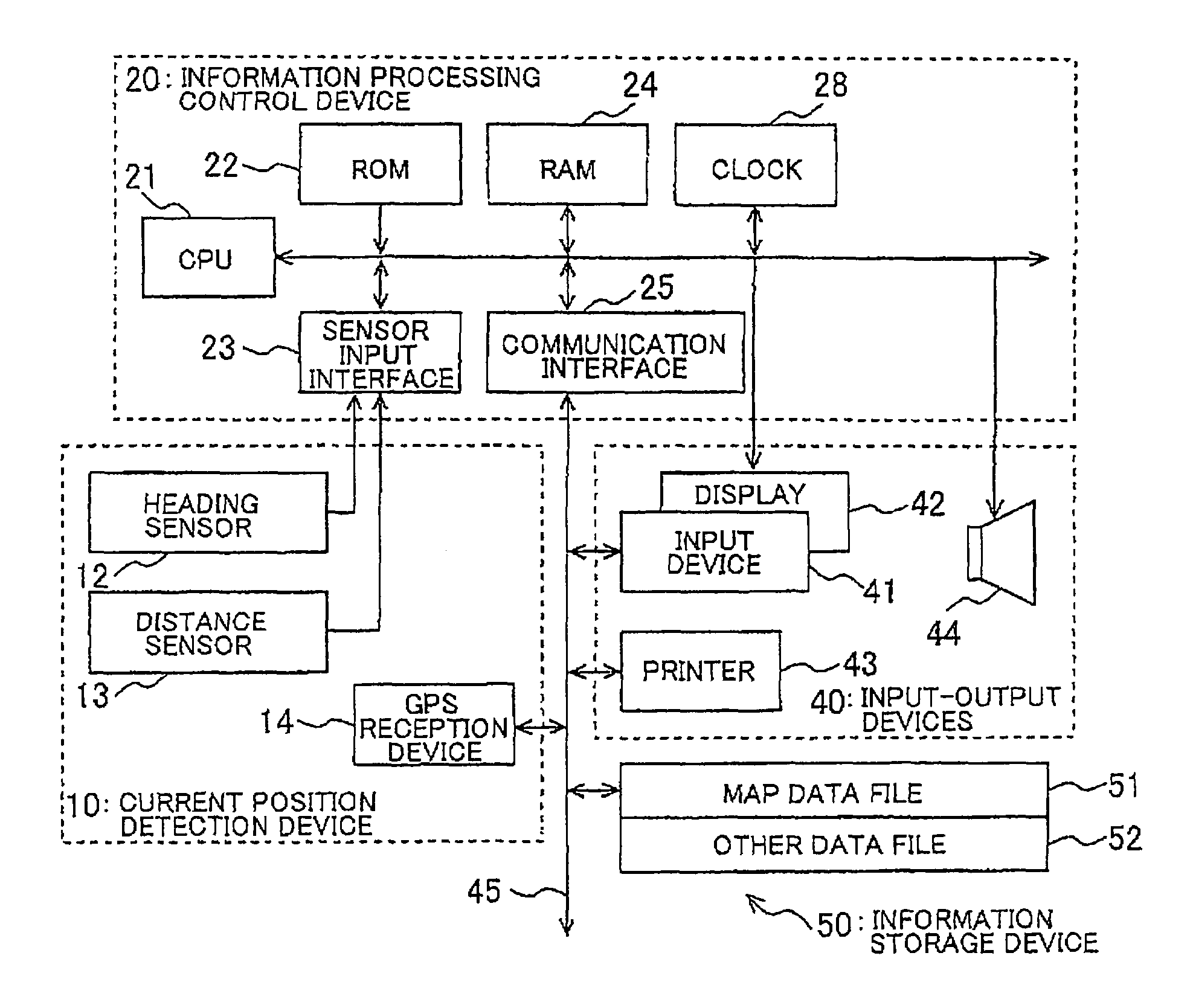
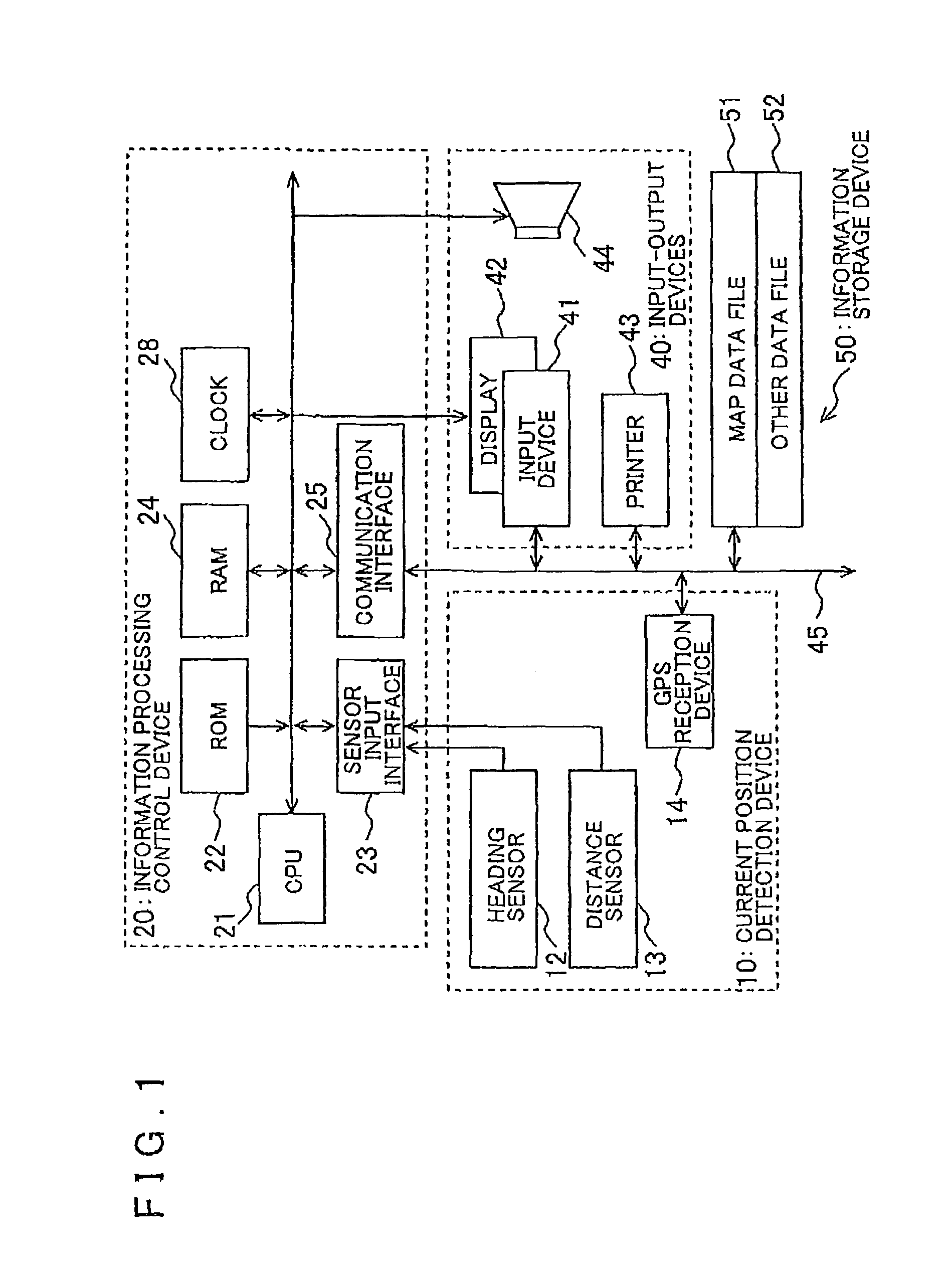
[0026]An example of a navigation device and a navigation program will be described in detail below with reference to FIGS. 1 to 12.

I. Overview of the Example

[0027]Surely matching to the correct road after passing a narrow angle branching is difficult using dead reckoning navigation alone. Therefore, in the navigation device of the present example, a cost calculation for each candidate point adds a GPS cost (correction cost) that corresponds to a distance from GPS coordinates to a normal cost according to a normal cost calculation to promptly recover matching to the correct road. In such case, the GPS coordinates may have errors, or the vehicle may be traveling at a position on a wide road that is distant from a database link. Therefore, the cost is also calculated in consideration of the GPS reliability and the road width.

[0028]The normal cost in map matching is calculated as follows. A movement distance and travel heading of the vehicle is detected by a distance sensor and a relati...


PUM


Abstract

Devices, methods, and programs identify a leading candidate point by calculating a cost for candidate points on a road, and match a vehicle position to the identified leading candidate point. The devices, methods, and programs acquire an estimated vehicle position based on dead reckoning navigation, acquire a GPS position of the vehicle, and set the candidate points for the vehicle position on nearby roads. The devices, methods, and programs calculate for each candidate point a normal cost of the candidate point with respect to the estimated position and a correction cost that corresponds to a value L1 (the value L1 being found by subtracting a width W of a road having the candidate point from a distance d between the GPS position and the candidate point), and identify the leading candidate point based on a total cost of the normal cost and the correction cost for each candidate point.

Description

INCORPORATION BY REFERENCE[0001]The disclosure of Japanese Patent Application No. 2009-043791, filed on Feb. 26, 2009, including the specification, drawings and abstract is incorporated herein by reference in its entirety.BACKGROUND[0002]1. Related Technical Fields[0003]Related technical fields include navigation devices, methods, and programs that perform map matching for navigation.[0004]2. Related Art[0005]On-vehicle navigation devices that find a travel route to a destination and guide the vehicle are widely used. This type of navigation device identifies the current position of the vehicle, displays the vehicle's current position on a map, and provides travel guidance. Types of sensors used for identifying the current position include gyro, vehicle speed pulse, and acceleration sensors, and an estimated path is generated from the sensor information using dead reckoning navigation. Shape matching of the estimated path and road information stored in a database is performed, and a...

Claims


Application Information

Patent Timeline
Patent Type & Authority Patents(United States)
IPC IPC(8): G01C21/00G01C21/26G01C21/28G01C21/30
CPCG01S19/49G01C21/30
Inventor OOHASHI, YUSUKESAKAKI, DAISUKEANDO, YOHEI
Owner AISIN AW CO LTD
Why Eureka
Try Eureka