Isolating decoupler

a decoupler and isolation technology, applied in the direction of interengaging clutches, gearing, hoisting equipment, etc., can solve the problems of fatigue fracture, catalytic failure, and difficulty in ensuring the safety of the crankshaft,

Active Publication Date: 2013-08-13
THE GATES CORP
View PDF10 Cites 43 Cited by
  • Summary
  • Abstract
  • Description
  • Claims
  • Application Information

AI Technical Summary

Problems solved by technology

At the same time torque requirement is substantially higher as well as challenges for all other elements of the crankshaft isolator.
Although beneficial during engine operation, the presence of the device on the crankshaft during start-up and shut down can present challenges.
This causes large deformations of the elastic element and can result in fatigue fractures and catastropic failure.

Method used


Image

  • Isolating decoupler
  • Isolating decoupler
  • Isolating decoupler

Examples


Embodiment Construction

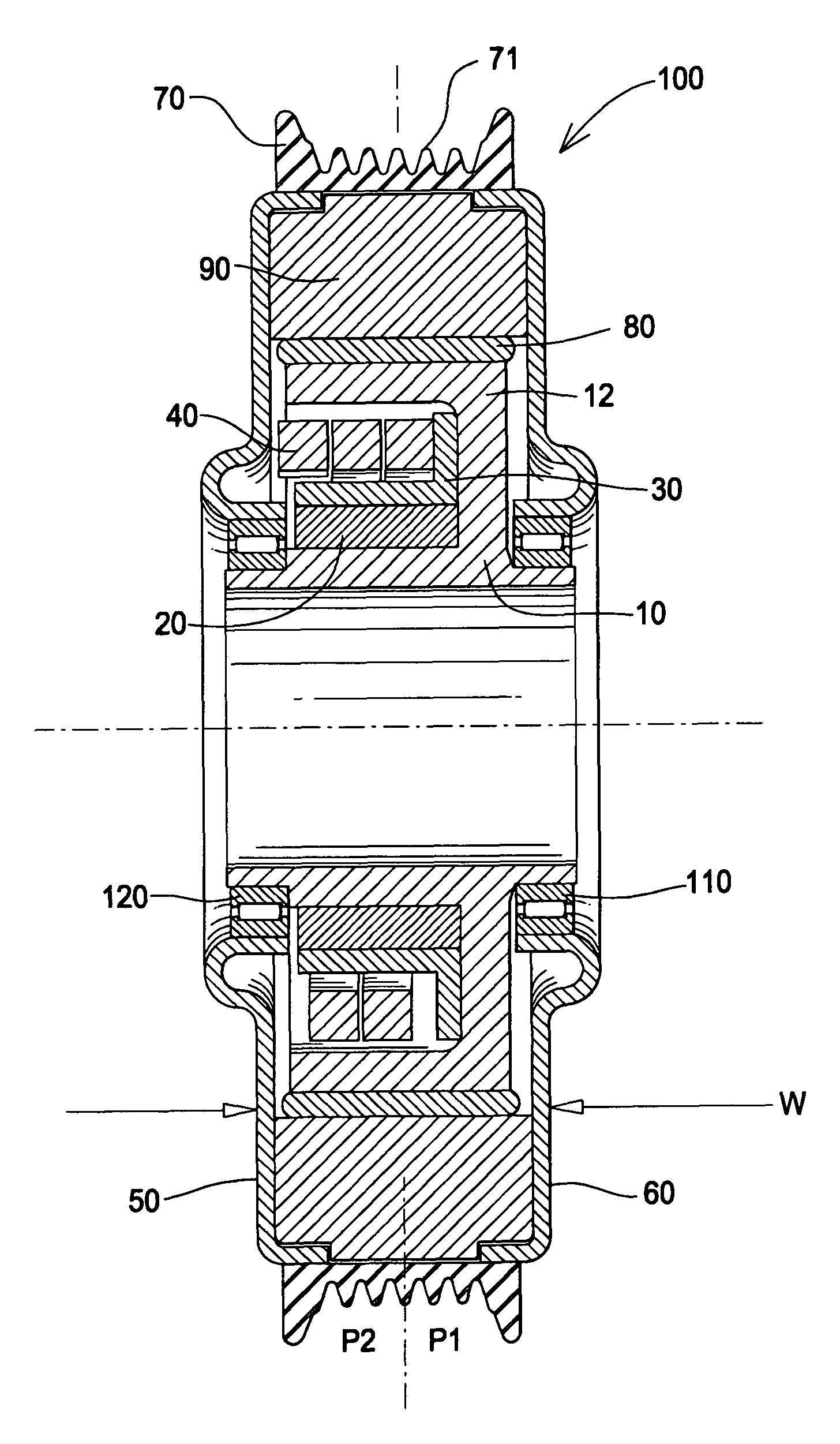
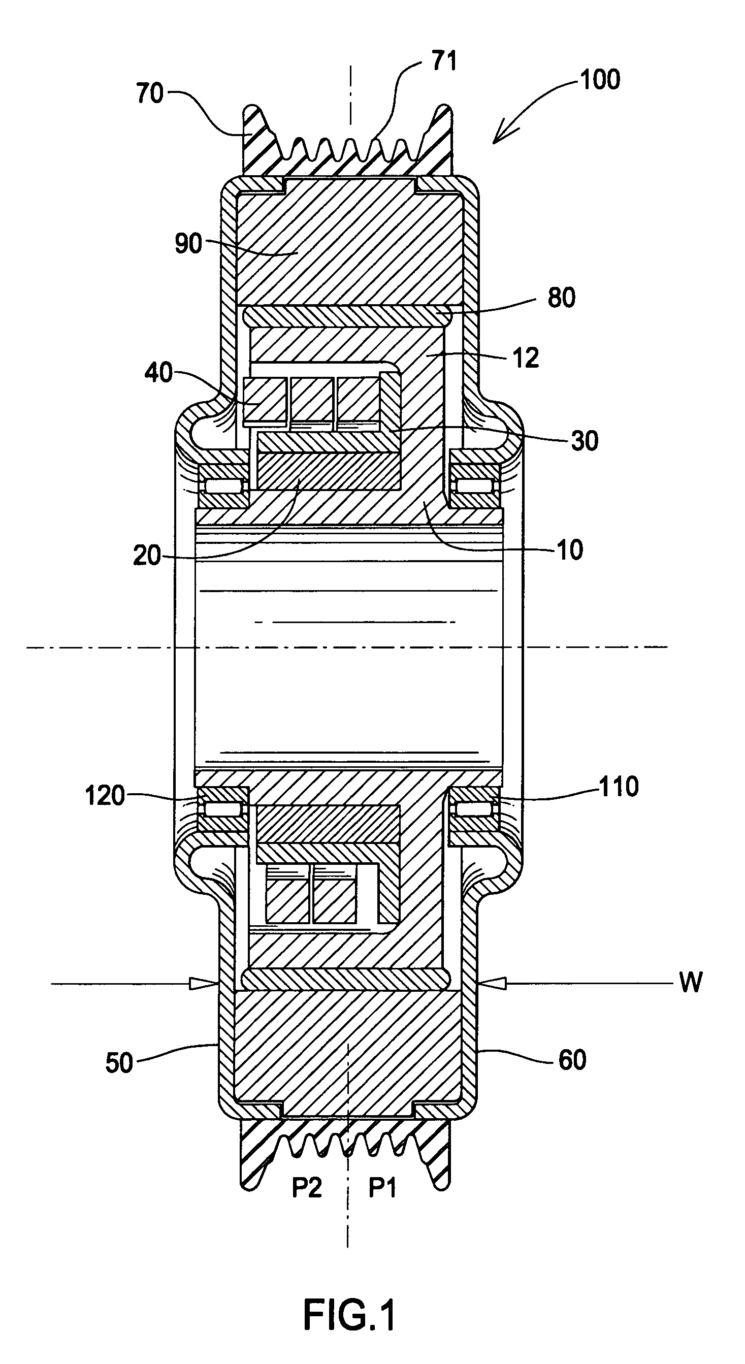
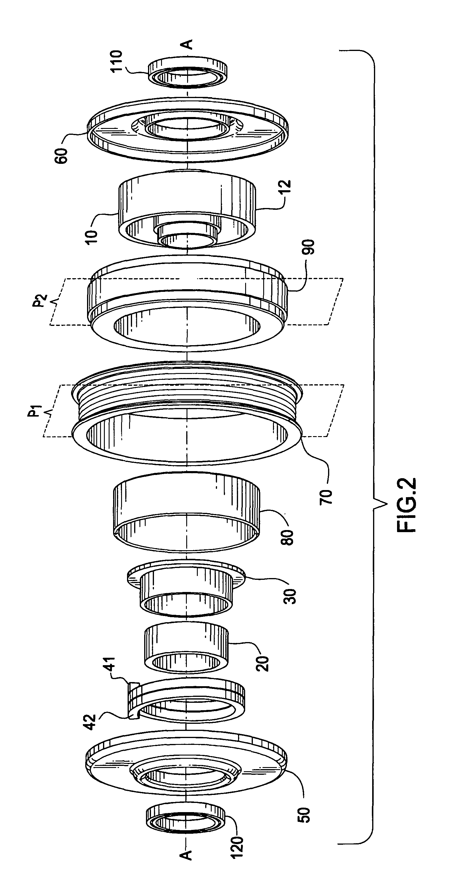
[0016]FIG. 1 is a cross-section of the device. The isolating decoupler comprises a hub 10. Hub 10 can be mounted to a shaft such as a crankshaft or driven accessory shaft (not shown).

[0017]A one-way clutch 20 is mounted to the hub 10. One-way clutch 20 is typically press fit onto the clutch carrier 30. The clutch 20 engages a hub 10.

[0018]A first end 41 of torsion spring 40 is connected to clutch carrier 30. The second end 42 of torsion spring 40 is connected to a pulley support member 50.

[0019]Pulley 70 is mounted to pulley support 50 and pulley support 60. Pulley 70 comprises a belt engaging surface 71.

[0020]Elastomeric ring 80 is connected to hub 10. Inertia ring 90 is connected to elastomeric ring 80. The inertia ring combined with the elastomeric ring damp crankshaft oscillations and vibrations caused during engine operation. Elastomeric ring 80 is securely fixed between inertia ring 90 and hub 10 using known adhesives, or mechanical, or press fit.

[0021]Pulley assembly 50, 60, ...


PUM


Abstract

An isolating decoupler comprising a hub, a one-way clutch engaged with the hub, a pulley rotationally engaged with the hub, a spring operationally engaged between the one-way clutch and the pulley, and an inertia member engaged with the hub through an elastomeric member, the inertia member substantially disposed within a width of the pulley, the inertia member moveable independently of the pulley.

Description

FIELD OF THE INVENTION[0001]The invention relates to an isolating decoupler, and more particularly, to an isolating decoupler having a one-way clutch and an inertia member attached to the hub, all contained within a pulley width.BACKGROUND OF THE INVENTION[0002]Vehicle internal combustion engines typically comprise a front end belt driven accessory drive. The accessories can include power steering, an alternator, water pump and so on. The accessory drive can also be referred to as a serpentine drive since the belt often traces a circuitous path about the front plane of an engine.[0003]A typical serpentine drive system includes a driving pulley on the crankshaft of an internal combustion engine of the vehicle, a series of driven pulleys for the accessories and a poly-V belt trained about the driving and driven pulleys. An advantage of the serpentine drive is that by providing an automatic belt tensioner on the belt the accessories can be fixedly mounted.[0004]It is also known to prov...

Claims


Application Information

Patent Timeline
Patent Type & Authority Patents(United States)
IPC IPC(8): F16H7/02F16F15/26F16D3/66
CPCF16D47/02F16D47/04F16H55/36F16F15/1213F16H2055/366F16D3/12F16D3/72F16F15/121
Inventor HARVEY, JOHN
Owner THE GATES CORP
Why Eureka
Try Eureka