X-ray tube with improved vacuum processing

a vacuum processing and x-ray tube technology, applied in the field of x-ray tube radiation sources, can solve the problems of x-ray tube failure, tube failure, and tube failure in the end

Active Publication Date: 2013-08-13
GENERAL ELECTRIC CO
View PDF8 Cites 2 Cited by
  • Summary
  • Abstract
  • Description
  • Claims
  • Application Information

AI Technical Summary

Problems solved by technology

Given the demanding schedules to which X-ray tubes are often subjected, failure of the tubes is of particular concern.
Further sources of X-ray tube failure occur during post-processing use due to leaks, degradation in the cathode or anode materials, and so forth, where particulates may be created or freed within the tube.
These particulates may result in eventual failure of the tubes over time.

Method used


Image

  • X-ray tube with improved vacuum processing
  • X-ray tube with improved vacuum processing
  • X-ray tube with improved vacuum processing

Examples


Embodiment Construction

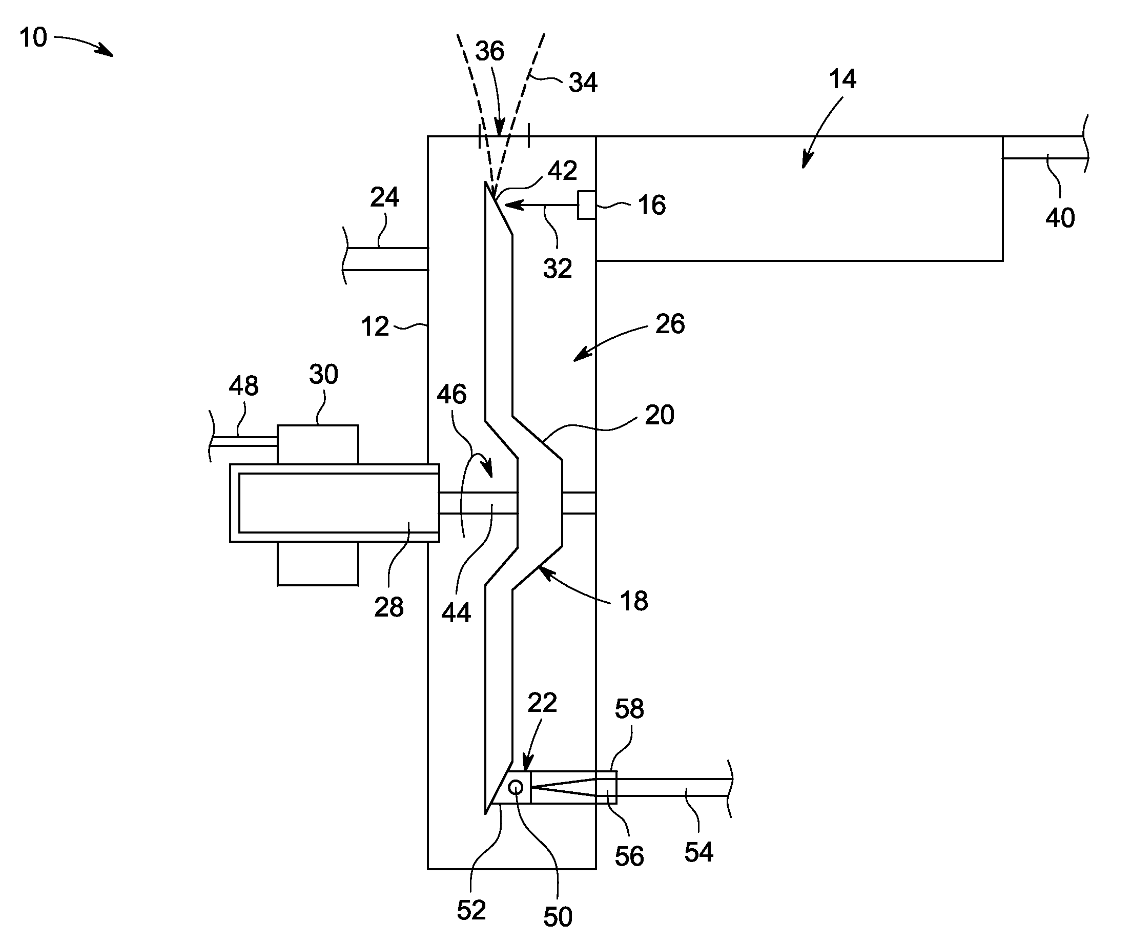
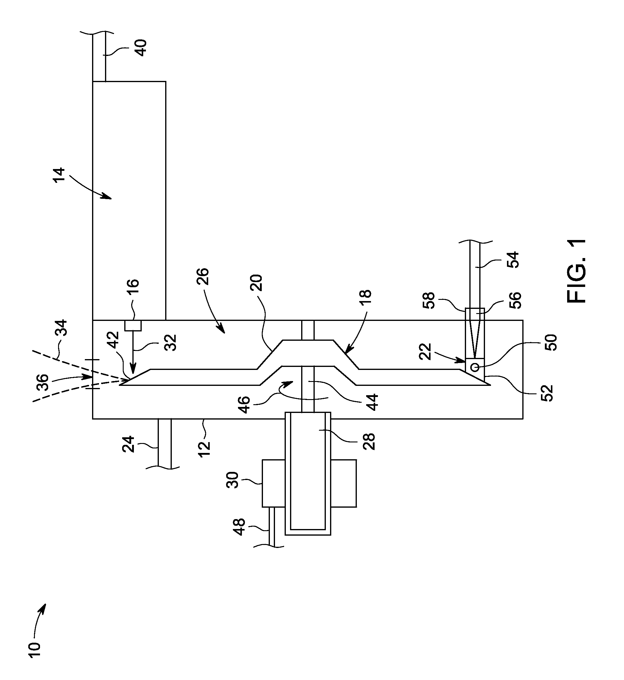
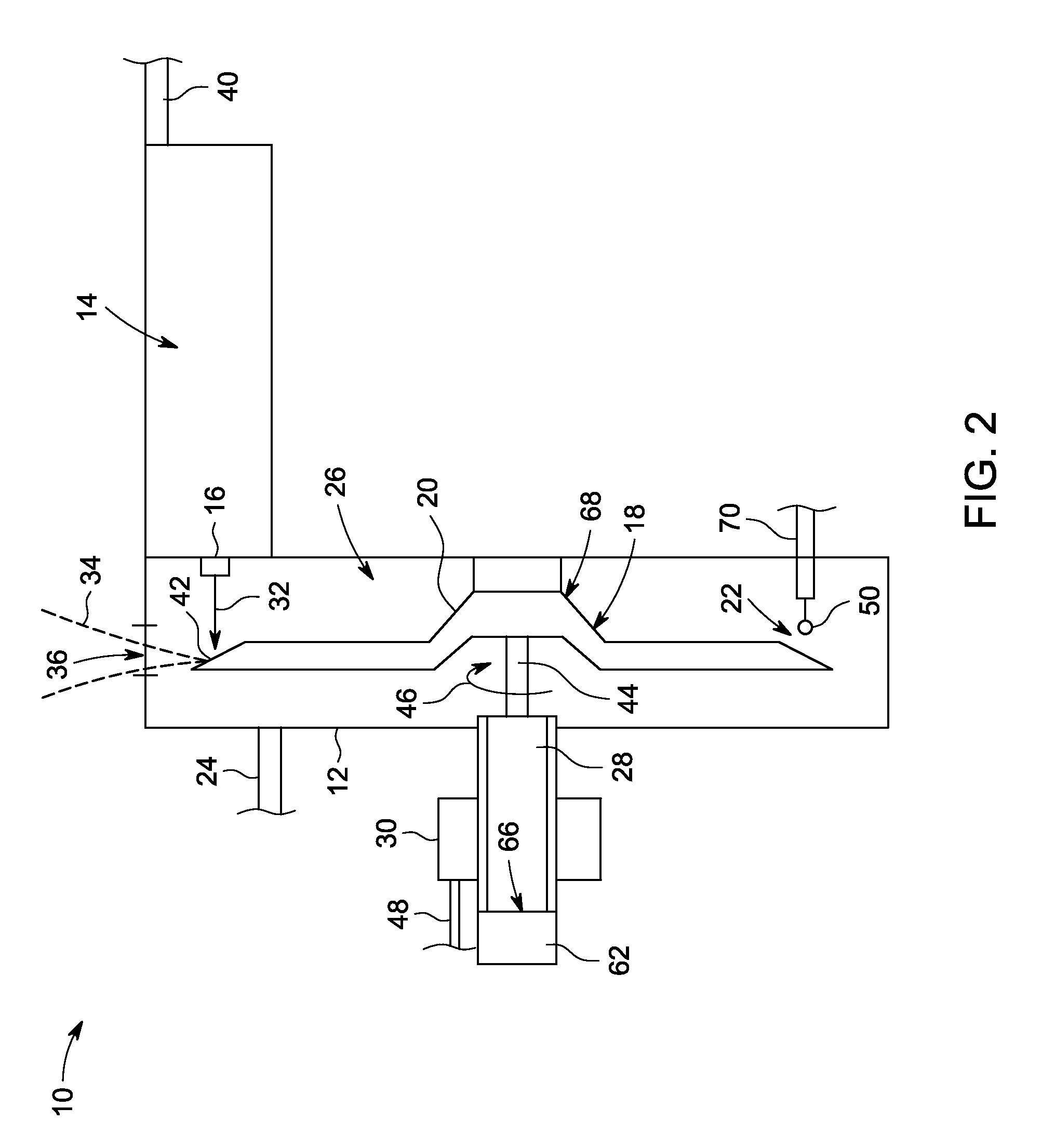
[0014]The present approaches are directed to the integration of a secondary cathode within X-ray tubes. The secondary cathode may be employed in processing the X-ray tube. More specifically, during X-ray tube processing the secondary cathode employed in the present approaches may be heated by an electrical current resulting in the emission of electrons from the secondary cathode towards an anode and degassing of the X-ray tube. The use of the secondary cathode for degassing spares the use of the X-ray tube primary cathode during processing and may extend the life of the primary cathode. In addition, the secondary cathode may be used to detect vacuum integrity within the X-ray tube during processing and post-processing and to act as a diagnostic tool for potential X-ray tube errors and failures related to high pressure.

[0015]According to the present approaches, the secondary cathode may eliminate the need for the standard bakeout technique used to process X-ray tubes, and / or shorten ...


PUM


Abstract

In one embodiment, an X-ray tube includes an electron beam source including a primary cathode configured to emit an electron beam and an anode assembly including an anode configured to receive the electron beam and to emit X-rays when impacted by the electron beam. The X-ray tube also includes an enclosure, at least the primary cathode and the anode being disposed in the enclosure, and a secondary cathode disposed in the enclosure and configured to emit electrons to impact the anode for degassing the enclosure.

Description

BACKGROUND OF THE INVENTION[0001]The subject matter disclosed herein relates to X-ray tube radiation sources and more particularly to the processing of X-ray tubes.[0002]In non-invasive imaging systems, X-ray tubes are used in projection X-rays systems, fluoroscopy systems, tomosynthesis systems, and computer tomography (CT) systems as a source of X-ray radiation. Typically, the X-ray tube includes a cathode and an anode. An emitter within the cathode emits a stream of electrons in response to heat resulting from an applied electrical current via the thermionic effect. The anode includes a target that is impacted by the stream of electrons. The target, as a result, produces X-ray radiation and heat. Such systems are useful in medical contexts, but also for parcel and package screening, part inspection, various research contexts, and so forth.[0003]The radiation traverses a subject of interest, such as a human patient, and a portion of the radiation impacts a detector or photographic...

Claims


Application Information

Patent Timeline
Patent Type & Authority Patents(United States)
IPC IPC(8): H01J35/20
CPCH01J35/06H01J35/20H01J2235/20H01J35/064H01J35/066
Inventor TANG, LIANGBIEHR, ERIC BRUCEROFFERS, RICHARD MICHAELKOPPISETTY, KALYAN
Owner GENERAL ELECTRIC CO
Why Eureka
Try Eureka