Noise cancelling microphone with reduced acoustic leakage

a microphone and acoustic leakage technology, which is applied in the field of noise cancellation microphones with reduced acoustic leakage, can solve the problems of affecting the noise cancellation ability of the headset, the acoustic paths between the speaker and the microphone diaphragm are impairing communication on delayed lines, and other microphone designs, such as certain specialty hearing aid designs that do not utilize a pcb with electrical leads attached, and are therefore more expensiv

Active Publication Date: 2013-08-13
PLANTRONICS
View PDF0 Cites 10 Cited by
  • Summary
  • Abstract
  • Description
  • Claims
  • Application Information

AI Technical Summary

Problems solved by technology

All other acoustic paths between the speaker and the microphone diaphragm impair communications on delayed lines.
Other microphone designs, such as certain specialty hearing aid designs do not utilize a PCB with electrical leads attached and are therefore more expensive.
Inadequate acoustic seal between the boots and microphone, referred to as acoustic leakage, impairs the noise cancellation ability of the headset.
Maintaining adequate seal between the two boots and around microphone wires has always been a challenge.
This requirement increases the challenge of maintaining an adequate acoustic seal in the rear cavity.
Furthermore, the headset PCB may not have sufficient room for an opening if it is populated with circuit components.
In this case, a noise canceling microphone cannot be used.
This has proven difficult to achieve consistently in production.
In addition, the volume of the rear cavity changes with the variations in the precise location of the isolation plug inside the boom shaft, resulting in variations in frequency response and noise cancellation performance.
Pulling the microphone wires through the isolation plug during assembly is a difficult and time consuming process.
Despite these previous solutions, achieving adequate acoustic seal between the acoustic components of noise canceling headsets continues to present design and manufacturing challenges.

Method used


Image

  • Noise cancelling microphone with reduced acoustic leakage
  • Noise cancelling microphone with reduced acoustic leakage
  • Noise cancelling microphone with reduced acoustic leakage

Examples


Embodiment Construction

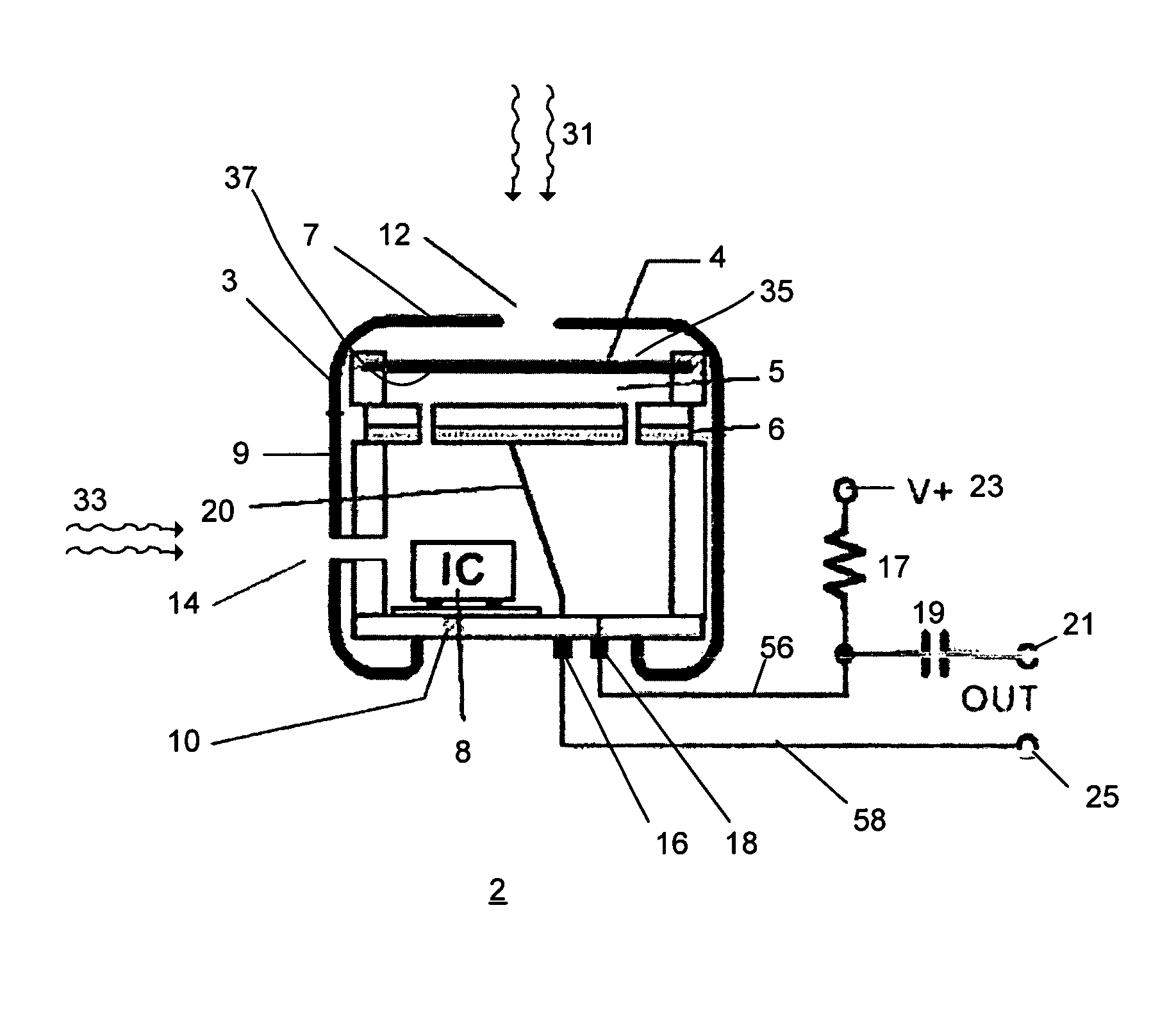
[0025]Methods and apparatuses for a noise canceling microphone system are disclosed. The following description is presented to enable any person skilled in the art to make and use the invention. Descriptions of specific embodiments and applications are provided only as examples and various modifications will be readily apparent to those skilled in the art. The general principles defined herein may be applied to other embodiments and applications without departing from the spirit and scope of the invention. Thus, the present invention is to be accorded the widest scope encompassing numerous alternatives, modifications and equivalents consistent with the principles and features disclosed herein. For purpose of clarity, details relating to technical material that is known in the technical fields related to the invention have not been described in detail so as not to unnecessarily obscure the present invention.

[0026]Generally, this description describes a method and apparatus for a nois...


PUM


Abstract

Systems and methods for a noise canceling microphone and microphone system are disclosed. The system generally includes a housing with a printed circuit board forming a surface of the housing. Electrical terminals are located on an exterior side of the printed circuit board. A diaphragm is disposed within the housing. A first port in the housing remote from the printed circuit board provides access to one face of the diaphragm first face and a second port disposed in the housing remote from the printed circuit board provides access to a second face of the diaphragm.

Description

BACKGROUND OF THE INVENTION[0001]Electret Condenser Microphones (ECM) used in communications headsets are often housed in elastomeric components called boots. The primary function of a microphone boot is to create an acoustic seal with the microphone so that only the sound entering from the acoustic port(s) located on the external surfaces of the headset or microphone boom can reach the microphone diaphragm. All other acoustic paths between the speaker and the microphone diaphragm impair communications on delayed lines. A secondary function of a microphone boot is to act as a resonator for frequency response shaping.[0002]Microphone assemblies used in telephonic devices and headsets include a microphone transducer, sound port(s), and a housing containing the signal processing circuitry. This invention relates to microphones with two sound ports (i.e., gradient microphones, also known as noise canceling microphones). Referring to FIG. 1, a prior art noise canceling microphone assembl...

Claims


Application Information

Patent Timeline
Patent Type & Authority Patents(United States)
IPC IPC(8): H04R3/00
CPCH04R3/06H04R19/016H04R1/1075H04R1/1083H04R2201/107H04R1/38
Inventor ISVAN, OSMAN K.
Owner PLANTRONICS
Why Eureka
Try Eureka