Metal joint and building comprising the same

a technology of metal joints and building components, applied in the field of metal joints, can solve the problems of reducing the bending yield of the bending panel or the shear and improving the degree of freedom, reducing the horizontal strength of the entire building, and reducing the bending yield of the bending panel

Active Publication Date: 2013-08-20
NIPPON STEEL CORP
View PDF32 Cites 15 Cited by
  • Summary
  • Abstract
  • Description
  • Claims
  • Application Information

AI Technical Summary

Benefits of technology

[0053]According to the building including a metal joint disclosed in (1) or the like, it is possible to achieve a building that effectively absorb energy caused by an earthquake or the like and is economical and excellent in earthquake resistance. Further, degree of freedom is improved in installing the metal joint and reinforcement for members provided around the metal joint is reduced or omitted, so that the manufacturing cost may be reduced.
[0054]According to the metal joint disclosed in (16) or the like, it is possible to achieve a building that effectively absorb energy caused by an earthquake or the like and is economical and excellent in earthquake resistance, and to improve the mountability or maintainability of the metal joint.

Problems solved by technology

As a result, there is a problem in that the horizontal strength of the entire building is decreased.
Further, when a tensile force is applied in a direction where the column rises due to an earthquake or the like, the bending yield of the bending panel or the shear yield of the shear panel occurs.

Method used


Image

  • Metal joint and building comprising the same
  • Metal joint and building comprising the same
  • Metal joint and building comprising the same

Examples


first embodiment

[0126]A first embodiment of the present invention will be described below with reference to drawings.

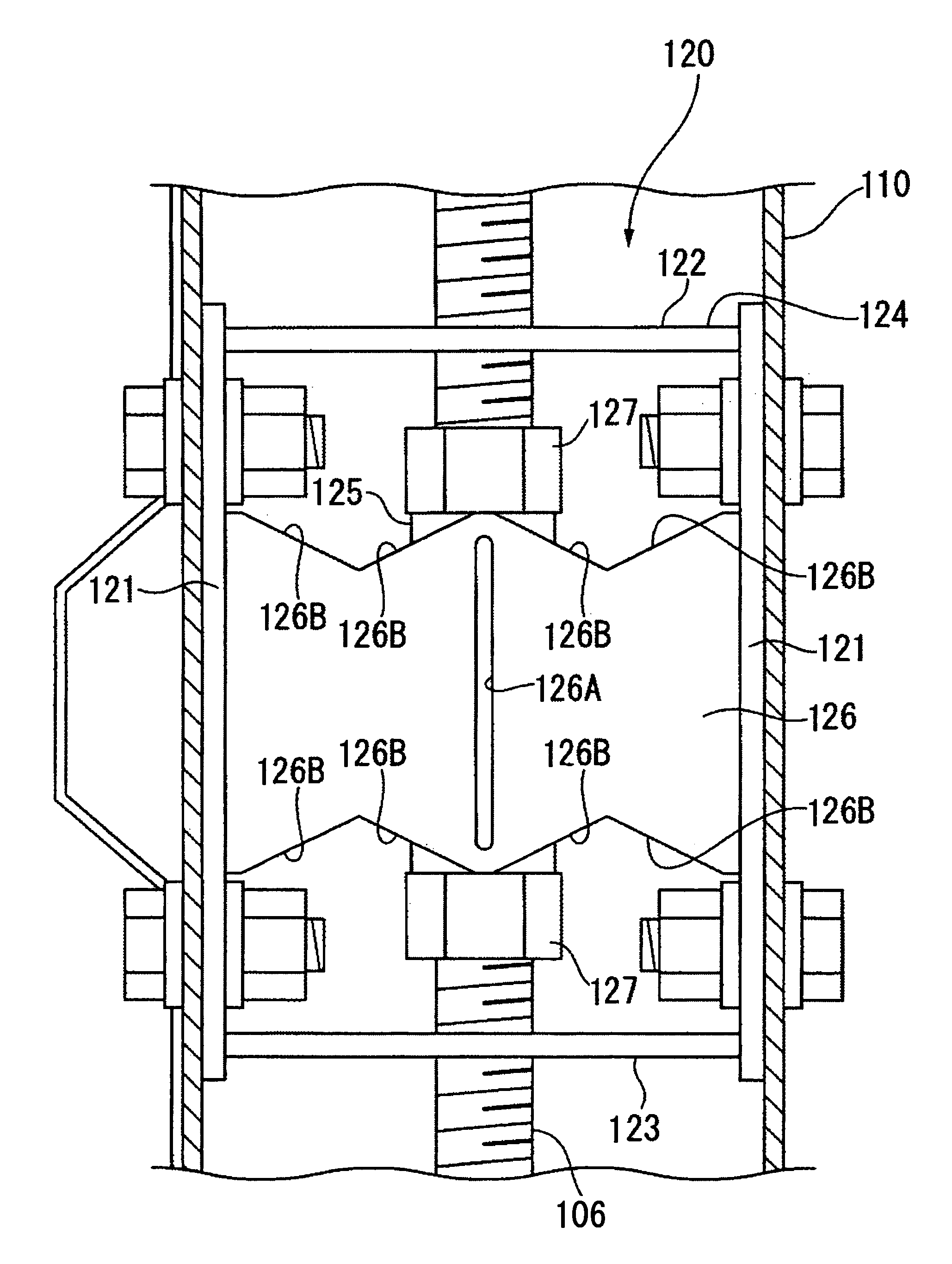
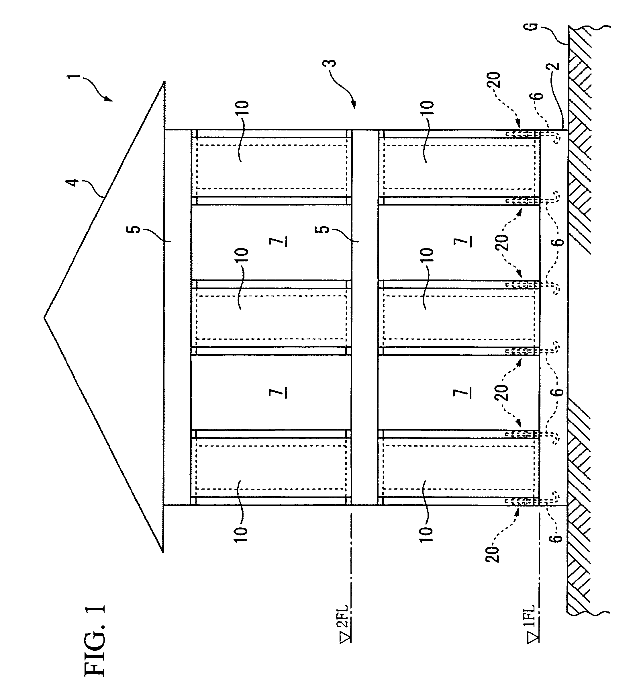
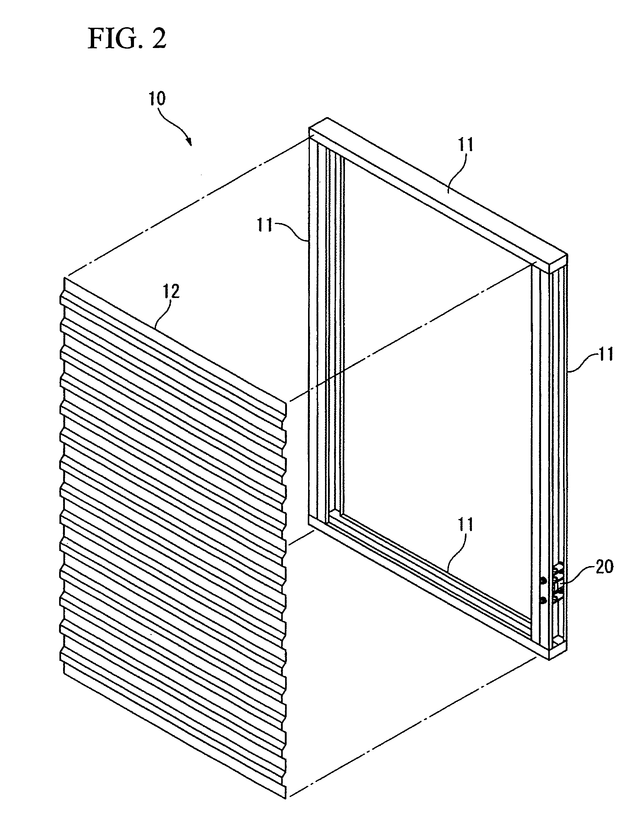
[0127]FIG. 1 is a front view showing the schematic construction of a building 1, which is constructed by a wood frame construction method, according to this embodiment. FIG. 2 is an exploded perspective view of a bearing wall 10 of the building 1 that is constructed by a wood frame construction method. FIG. 3 is a perspective view showing a connection portion between the bearing wall 10 and a foundation 2.

[0128]In FIGS. 1 to 3, the building 1, which is constructed by a wood frame construction method, is a two-story house including a foundation 2 that is constructed on the ground G and is made of reinforced concrete, a building body 3 that is fixed to the foundation 2, and a roof 4 that is provided to cover an upper portion of the building body 3.

[0129]The building body 3 includes a plurality of bearing walls 10 that is provided on floor, beams 5 that are provided at positions corresp...

second embodiment

[0151]A second embodiment of the present invention will be described below with reference to FIGS. 8 to 10.

[0152]FIGS. 8 to 10 are perspective views showing a part of a building including a metal joint according to this embodiment of the present invention.

[0153]In FIGS. 8 to 10, metal joints 50 are mounted on a column leg of a column 51 that is installed on a building foundation 2, and exert a damping effect by the rocking or rise of the column 51. The metal joint 50 has substantially the same construction as each of the metal joints 20, 30, and 40 according to the first embodiment. The metal joint includes a cylindrical steel member 52 that is a first connecting part connected to an anchor bolt 6, that is, an anchor member which is fixed to the building foundation 2 and extends upward; a fixing piece 53 that is a second connecting part connected to the column 51; and a pair of damper steel plates 54 that is damping members joined to the cylindrical steel member 52 and the fixing pi...

third embodiment

[0155]A third embodiment of the present invention will be described below with reference to FIGS. 11 and 12A to 12C.

[0156]FIG. 11 is a perspective view showing a part of a building including a metal joint according to this embodiment.

[0157]In FIG. 11, metal joints 60 are mounted to the ends of the beams 62 at column-beam joint portions 63 where a column 61 of a building is joined to beams 62, and exert a damping effect by the expansion and contraction of upper and lower flanges 64 that are caused by the bending of the beams 62. The metal joint 60 has substantially the same construction as each of the metal joints 20, 30, 40, and 50 according to the first and second embodiments. The metal joint includes a cylindrical steel member 65 that is a first connecting part connected to an anchor bolt 6, that is, an anchor member which is fixed to the column 61 or the end of each of the beams 62 that face each other with the column 61 interposed therebetween; a fixing piece 66 that is a second...


PUM


Abstract

A building including a metal joint is provided with a damping member that is mounted between at least a pair of structures and yields in accordance with relative displacement between the structures. The damping member includes strength-suppression device that suppresses an increase of strength after yield, and exerts a damping effect with rocking or expansion and contraction of at least one of the structures.

Description

TECHNICAL FIELD[0001]The present invention relates to a metal joint that exerts a damping effect in accordance with relative displacement between structures, and a building including the metal joint.[0002]The present application is based on: Japanese Patent Application No. 2008-14022; and Japanese Patent Application No. 2008-14023, and the entire contents thereof are incorporated herein.BACKGROUND ART[0003]Conventionally, a bearing wall where a face member is fixed to a frame made of wood or section steel has generally been used in a building that is constructed by a wood frame construction method and has two-by-four construction, woody wall panel construction, light-gauge steel construction, or the like. Further, the building, which is constructed by a wood frame construction method, bears a horizontal force (external force), which is applied to the building by an earthquake or wind, as a shear force of the face member of the bearing wall. Accordingly, the horizontal strength of th...

Claims


Application Information

Patent Timeline
Patent Type & Authority Patents(United States)
IPC IPC(8): E04B1/62E04F15/22E04F15/14E04B1/98E04H9/02E02D27/34E04B1/68
CPCE04B1/24E04B1/4157E04B2001/2415E04B2001/2442E04B2001/2454E04B2001/246E04B2001/2463E04B2001/2496F16F7/12E04H9/0237E04H9/0235E04H9/021F16F15/02E04H9/028E02D27/34E04B1/6803E04B1/681E04F15/22
Inventor KAWAI, YOSHIMICHITANAKA, HIROSHI
Owner NIPPON STEEL CORP
Why Eureka
Try Eureka