
Rotation control device for a tool

a technology of rotating control device and tool, which is applied in the direction of mechanical control device, rod connection, crowbar, etc., can solve the problems of reducing the efficiency of prying tools, and reducing the output torque, so as to avoid the problem of stuck fault and improve the convenience of us

Inactive Publication Date: 2013-08-20
SU CHENG WEI
View PDF15 Cites 23 Cited by
  • Summary
  • Abstract
  • Description
  • Claims
  • Application Information

AI Technical Summary

Benefits of technology

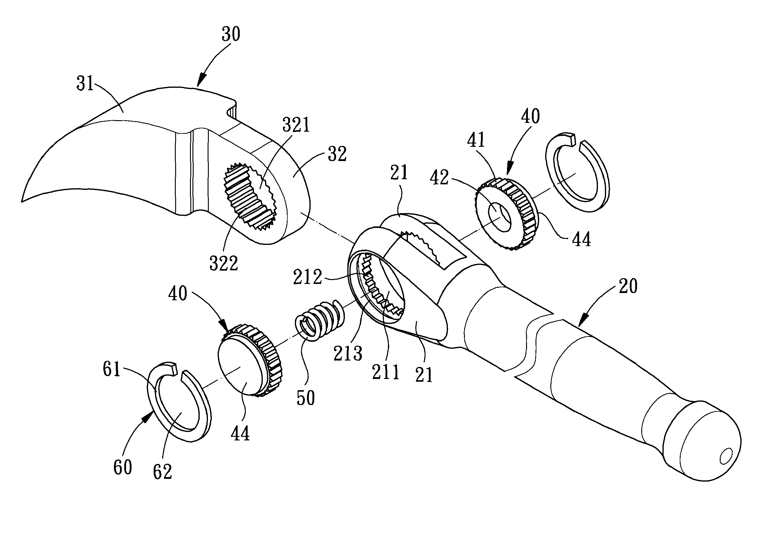
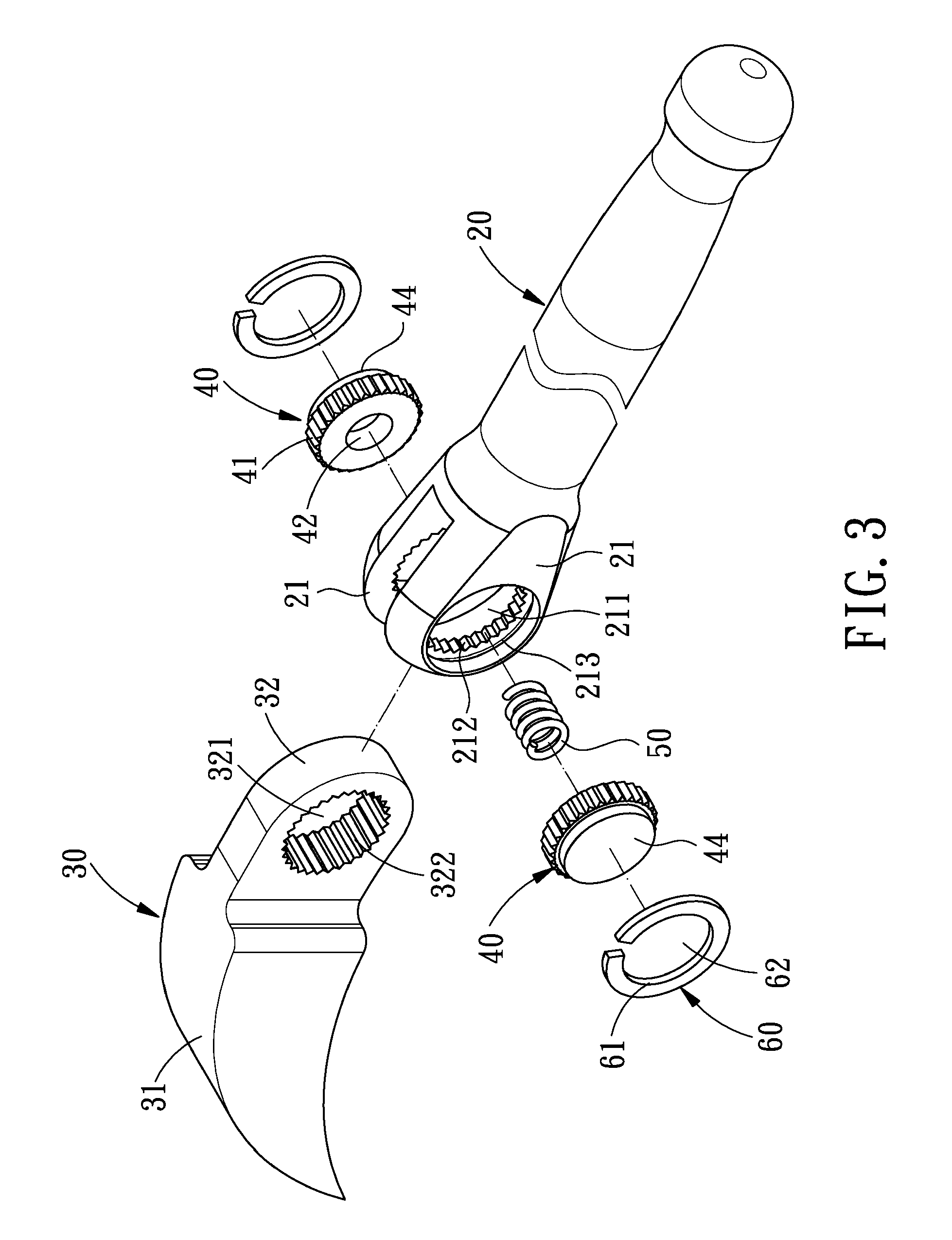
The present invention provides a rotation control device for a tool that can avoid the stuck fault and improve convenience in use. It also reduces cost and makes assembly easier. The device includes two ratchet wheels that can be pressed to compress the spring oppositely, which can be fully engaged with the tool head, so that it can be rotated to a desired angle. The two ratchet wheels are symmetrically arranged, so they can be subjected to the same force and move the same distance, thus avoiding the stuck fault while improving convenience in use.

Problems solved by technology

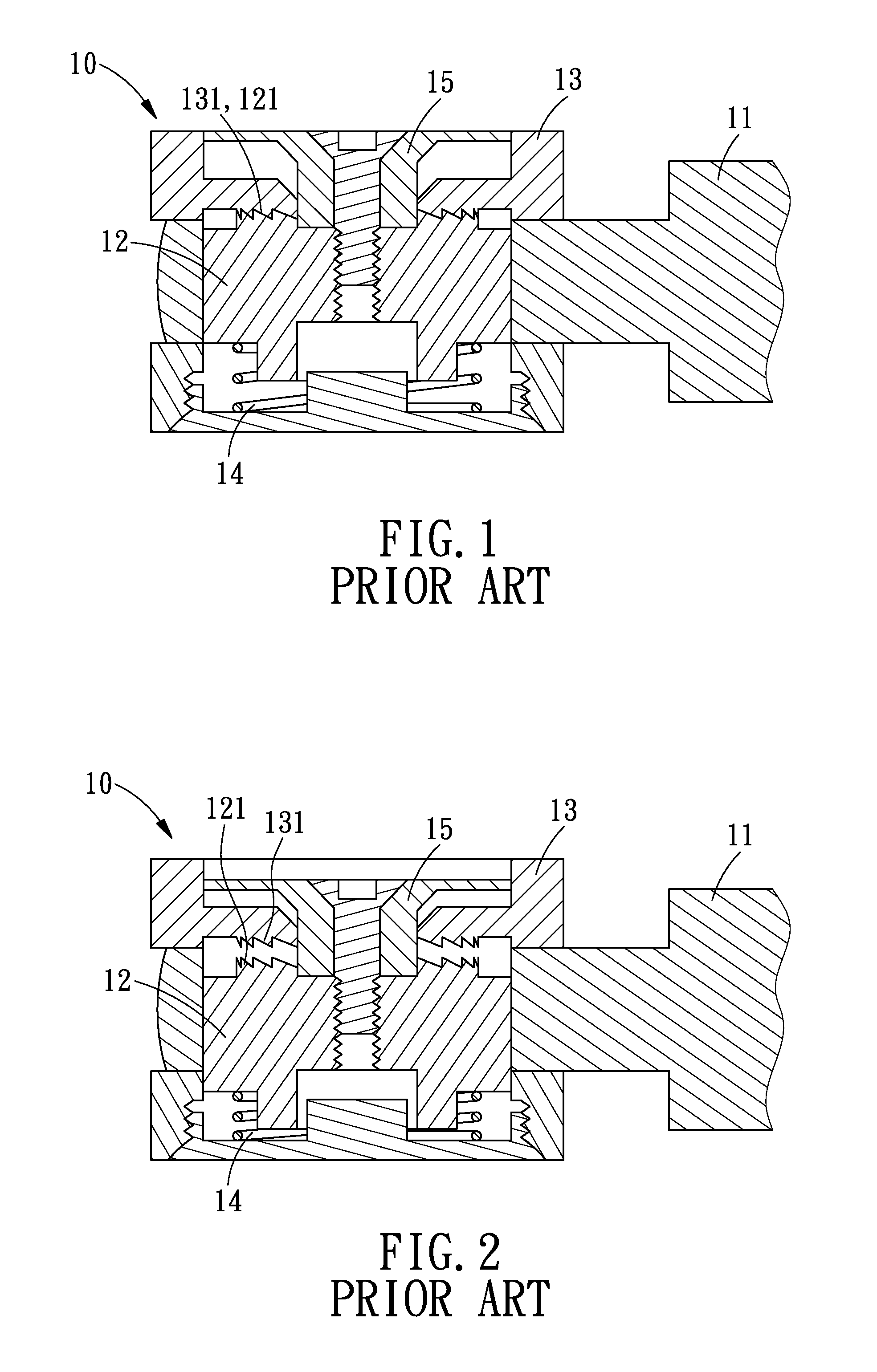
However, as the rotating block 12 engages with the prying head 13 while being elastically pressed by the spring 14, it is not easy for the engaging portion 121 of the rotating block 12 and the engaging portion 131 of the prying head 13 to engage with each other in a very exact and precise manner, which will cause inconvenience in use, or even stuck fault.
In addition, the single-flank engagement cannot provide enough engaging force, consequently reducing the output torque.
This pry tool is too complicated in structure, since it has many types of components.
Especially, the first serrated insert and the second serrated insert are two different sized components, which require different manufacturing procedures and, therefore, will increase manufacturing cost.
Otherwise, no angle adjustment can be made between the indexable body and the handle, causing inconvenience in assembly.

Method used


Image

  • Rotation control device for a tool
  • Rotation control device for a tool
  • Rotation control device for a tool

Examples


Embodiment Construction

[0026]The present invention will be clearer from the following description when viewed together with the accompanying drawings, which show, for purpose of illustration only the preferred embodiments in accordance with the present invention.

[0027]Referring to FIGS. 3-5, a rotation control device for a tool in accordance with a preferred embodiment of the present invention comprises a handle 20, a tool head 30, two ratchet wheels 40, a spring 50, and two C-shaped snap rings 60.

[0028]The handle 20 is formed with two opposite parallel assembling portions 21 at one end thereof. Each of the two assembling portions 21 is defined with a first through hole 211. Each of the first through holes 211 is provided with a first ratchet portion 212 on an inner periphery thereof, and an annular groove 213 close to an outer edge of the inner periphery thereof.

[0029]The tool head 30 includes a working portion 31 at one end thereof, and the other end of the tool head 30 is a pivot portion 32 to be pivot...


PUM


Abstract

A rotation control device for a tool is disposed between a handle and a tool head and includes two ratchet wheels, a spring and two C-shaped snap rings. The two ratchet wheels are symmetrically arranged. When pressed, the respective ratchet wheels will be subjected to the same force and move the same distance, thus making the engagement between the ratchet wheels and the tool head more assured, while avoiding the stuck fault and improving the convenience in use.

Description

CROSS REFERENCE[0001]This application is a continuation in part of U.S. patent application Ser. No. 12 / 621,490, filed Nov. 18, 2009 now abandoned.BACKGROUND[0002]1. Field of the Invention[0003]The present invention relates to a device for a tool and, more particularly, to a rotation control device for a tool.[0004]2. Description of the Prior Art[0005]Referring to FIGS. 1-2, a conventional rotational prying tool 10 comprises a handle 11, a rotating block 12 and a prying head 13. The rotating block 12 is disposed in the handle 11, and the prying head 13 is mounted on both the handle 11 and the rotating block 12. The prying head 13 is provided with an engaging portion 131 on an inner surface thereof; while the rotating block 12 is provided with a engaging portion 121 on an outer surface thereof. The engaging portion 131 can be engaged with the engaging portion 121. Between one side of the rotating block 12 and the prying head 13 is disposed a spring 14, and the other side of the rotati...

Claims


Application Information

Patent Timeline
Patent Type & Authority Patents(United States)
IPC IPC(8): F16D1/00F16L41/00F16D3/00
CPCB25G1/06B25G3/38Y10T403/32271Y10T74/2133Y10T403/32368Y10T403/32254Y10T403/32434
Inventor SU, CHENG-WEI
Owner SU CHENG WEI
Learn More