Enhanced precise location

a precise location and location technology, applied in the direction of mechanical measurement arrangements, mechanical roughness/irregularity measurements, instruments, etc., can solve the problems of harmful results, property damage, and often buried underground utilities

Active Publication Date: 2013-08-20
BUSAN TRANSPORTATION CORPORATION
View PDF7 Cites 6 Cited by
  • Summary
  • Abstract
  • Description
  • Claims
  • Application Information

AI Technical Summary

Problems solved by technology

Utility conduits are often buried underground and not readily accessible.
If these locations are not accurate for an excavation, harmful results may occur such as property damage, serious physical harm to a person, or even death.
In some cases, there may be bias in the targeted conductor's estimated centerline as a result of distortion due to bleedover.
In conventional receivers, it is very difficult to determine whether the receiver is tracking the targeted conductor or whether the receiver is erroneously tracking a neighboring conductor.

Method used


Image

  • Enhanced precise location
  • Enhanced precise location
  • Enhanced precise location

Examples


Embodiment Construction

[0025]The following exemplary embodiments describe using several parameters used by a line locator to more accurately locate a concealed line. These parameters can include the following:

a=[x,z,I,φ,dI,dφ]

[0026]where, x is the horizontal position of each line (whether it be the target line and / or any bleedover lines;

[0027]z is the vertical position (depth) of each line;

[0028]I is the current of each line;

[0029]φ is the phase for each line;

[0030]dI is the current difference between two nearest side tones; and

[0031]dφ is the phase difference between the two nearest side tones.

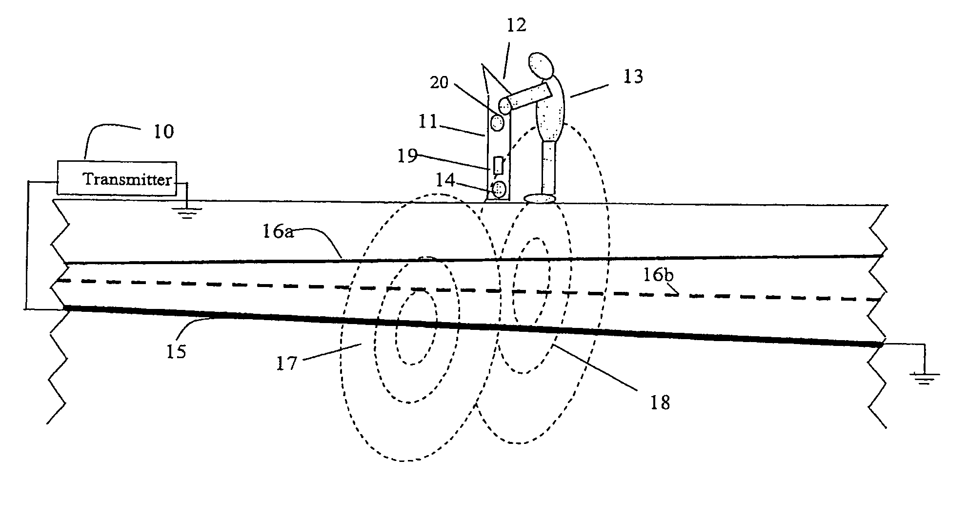
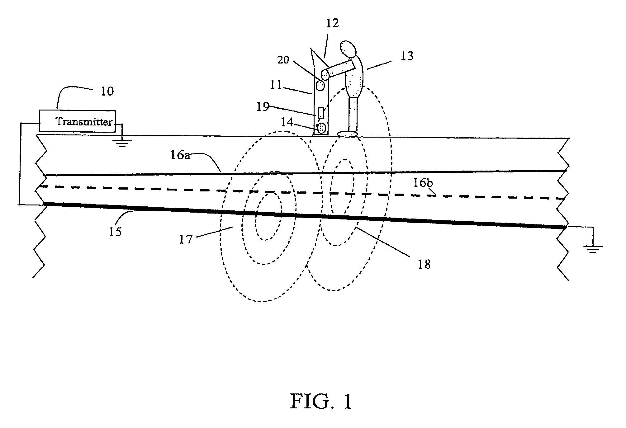
[0032]FIG. 1 illustrates a line location environment with a line locator 11 (also referred to as “receiver”). A target line 15 energized by an electric current from transmitter 10 emits an electromagnetic (EM) field 17. EM field 17 induces a current in nearby bleedover conductors such as lines 16a and 16b (collectively lines 16) because of resistive, inductive, or capacitive bleedover. The bleedover currents in lin...


PUM


Abstract

A method for determining the location of underground cables and pipes is disclosed. In some embodiments, the method includes measuring a set of electromagnetic field magnitudes and phases at a plurality of positions while traversing a target line parallelly using 3D electromagnetic coil sensors, the 3D electromagnetic coil sensors being orthogonally oriented to the target line, modeling a set of expected complex electromagnetic field magnitudes of a single underground conductor at each of the positions to form a set of values corresponding to a set of individual models for the target line, determining which of the set of individuals models is a best model, determining confidence information at each of the positions based on a comparison between the measured set of complex electromagnetic magnitudes and phases and the best model, and determining parameters at each of positions related to the target line from the best model.

Description

BENEFIT OF PRIORITY[0001]This application in a continuation-in-part of application Ser. No. 12 / 122,136, filed May 16, 2008 now U.S. Pat. No. 8,209,136, which claims the benefit of Provisional Application No. 60 / 930,753, filed May 18, 2007, both of which are incorporated herein by reference in their entirety. This application further claims the benefit of Provisional Application No. 60 / 993,741, filed Sep. 13, 2007, which is also which is incorporated herein by reference in its entirety.BACKGROUND[0002]1. Field of the Invention[0003]The present invention relates to detection of electromagnetic (EM) signals from targeted concealed conductors and, in particular, to the precise location of such conductors in the presence of signal distortion.[0004]2. Discussion of Related Art[0005]Utility conduits are often buried underground and not readily accessible. It is often necessary to locate these concealed utility conduits in order to repair and replace them. It is also important to know the l...

Claims


Application Information

Patent Timeline
Patent Type & Authority Patents(United States)
IPC IPC(8): G01B5/30
CPCG01R29/085G01V3/104G01V3/15G01V3/081G01V3/38
Inventor LI, KUNWAITE, JIMWELARATNA, RUWANOVERBY, JOHANSALVAGIONE, PAOLO
Owner BUSAN TRANSPORTATION CORPORATION
Why Eureka
Try Eureka