Laminoplasty apparatus and methods

a technology of laminoplasty and apparatus, applied in the field of laminoplasty, can solve the problems of difficult manipulation, small screws that can be lost, and require extremely small plates, and achieve the effect of simple yet effective adjustable laminoplasty implant and procedur

Inactive Publication Date: 2013-08-27
PATEL CHETAN +2
View PDF10 Cites 5 Cited by
  • Summary
  • Abstract
  • Description
  • Claims
  • Application Information

AI Technical Summary

Benefits of technology

[0005]This invention resides a simple yet effective adjustable laminoplasty implant and procedure. Broadly, a member is positioned within or through a hole formed through a spinous process, and an elongated element is provided with a medial end coupled to the member and a lateral end configured for engagement with a bone mass fixation device.

Problems solved by technology

Laminoplasty systems on the market today use simple bone plates for fixation and, due to the small area being plated, require extremely small plates.
These are often difficult to place and use very small screws that can be lost of difficult to manipulate.

Method used


Image

  • Laminoplasty apparatus and methods
  • Laminoplasty apparatus and methods
  • Laminoplasty apparatus and methods

Examples


Embodiment Construction

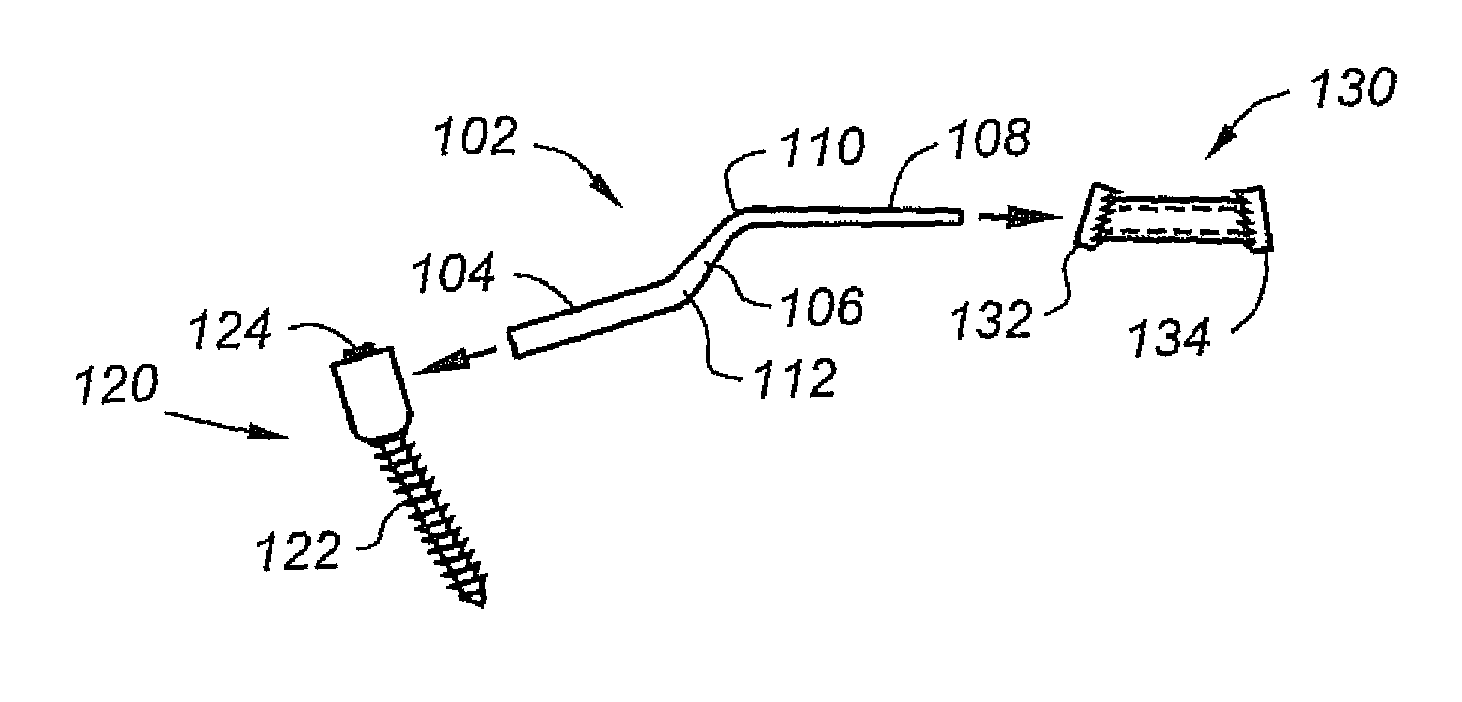
[0031]This invention improves upon laminoplasty devices and methods by providing a simple yet effective adjustable implant and procedure. One implant according to the invention, shown in FIG. 1, includes bent rod 1027, fixation screw 120, and sleeve 130. Rod 102 has a lateral end 104, midsection 106 and medial end 108. The diameter of the rod preferably necks down from a larger-diameter lateral end to a smaller-diameter medial end. The cross section of the rod is preferably circular throughout though non-round geometries may alternatively be used to resist rotation in certain directions, for example.

[0032]In this embodiment, rod 102 preferably includes two bends 110, 112 thereby forming right or obtuse angles between midsection 106 and ends 104, 108. The bends may be in the same plane or not depending upon patient physiology. Rod 102 may be provided with a predetermined shape and / or manipulated by the surgeon during the implantation procedure.

[0033]Sleeve 130 has an inner diameter s...


PUM


Abstract

A simple yet effective adjustable laminoplasty implant and procedure includes a member positioned within or through a hole formed through a spinous process, and an elongated element is provided with a medial end coupled to the member and a lateral end configured for engagement with a bone mass fixation device. The elongated element may be a bent rod. The rod may have a medial end with a cross-section that is smaller than that of the lateral end. The member positioned within or through a hole formed through a spinous process may be a sleeve with angled endcaps. The endcaps may include bone-engaging teeth. Alternatively, the sleeve may have a central bore and barbs that engage with surrounding bone when an elongated member is inserted in the bore. The mass fixation device may a pedicle screw. The pedicle screw may be configured to receive a transverse rod. Alternatively, the mass fixation device may itself be a rod. Method of performing a laminoplasty In accordance with the invention are also disclosed.

Description

BACKGROUND OF THE INVENTION[0001]This invention relates generally to laminoplasty and, in particular, to a simple yet effective adjustable implant and procedure.BACKGROUND OF THE INVENTION[0002]Laminoplasty is a surgical procedure for treating spinal stenosis by relieving pressure on the spinal cord. The procedure involves the cutting[0003](cutting through on one side and merely cutting a groove on the other) the lamina on both sides of the affected vertebrae and then “swinging” the freed flap of bone open thus relieving the pressure on the spinal cord. The spinous process may be removed to allow the lamina bone flap to be swung open. The bone flap is then propped open using small wedges or pieces of bone such that the enlarged spinal canal will remain in place.[0004]Often a small metal plate is used to bridge the open gap and help the bone graft remain in place. Laminoplasty systems on the market today use simple bone plates for fixation and, due to the small area being plated, req...

Claims


Application Information

Patent Timeline
Patent Type & Authority Patents(United States)
IPC IPC(8): A61B17/70
CPCA61B17/7071A61B17/7062
Inventor PATEL, CHETANTRUUMEES, EERICBROWN, HENRY
Owner PATEL CHETAN
Why Eureka
Try Eureka