Method and apparatus for correcting the uniformity of a magnetic field

a magnetic field and uniformity technology, applied in the field of magnetic resonance technology, can solve the problems of poor quality of scanned magnetic resonance images of tissues and organs, difficult to achieve, influence the doctor's subsequent analysis and diagnosis, etc., and achieve the effect of improving the image quality of the magnetic resonance imag

Active Publication Date: 2013-08-27
SIEMENS HEALTHCARE GMBH
View PDF2 Cites 2 Cited by
  • Summary
  • Abstract
  • Description
  • Claims
  • Application Information

AI Technical Summary

Benefits of technology

[0008]In view of the above situation, a primary object of the present invention is to provide a method for correcting the uniformity of a magnetic field, which is capable of properly implementing the correction of the uniformity of the magnetic field, thus further improving the imaging quality of the resulting magnetic resonance image.
[0009]Another object of the present invention is to provide an apparatus for correcting the uniformity of a magnetic field, which is capable of properly implementing a correction of the uniformity of the magnetic field, thus further improving the imaging quality of the resulting magnetic resonance image.
[0014]Preferably, the control unit has a calculating subunit and a setting subunit. The calculating subunit is used for calculating the voltage value to be provided in order to make the value of the shim current equal to the determined value of the shim current according to the known resistance of the active shim shell. The setting subunit is used for setting the output voltage value of the power supply provided to the active shim shell to the determined voltage value. The technical solution of the present invention determines the value to which the shim current in the active shim shell should be set so as to meet the uniformity requirements of the magnetic field according to the actual placement position of the active shim shell, and sets the shim current in the active shim shell according to the determined result. Compared with the prior art, the solution of the present invention has no strict requirements on the placement position of the active shim shell, thus avoiding the problem that the result of the correction to the uniformity of a magnetic field is not good enough due to errors caused by human operation or other reasons, and thereby the imaging quality of the magnetic resonance image is improved.

Problems solved by technology

For acquiring MR data from certain tissues and organs, such as the shoulder or chest, etc., since a patient lies flat on the patient bed, which passes through the magnet, these organs are located in the non-central areas of the magnet and, accordingly, the quality of the scanned magnetic resonance images of these tissues and organs is relatively poor, thus influencing the doctor's subsequent analysis and diagnosis.
If the uniformity of a magnetic field needs to be corrected for all the non-central areas of a magnet, this is generally quite difficult to accomplish and is associated with relatively high costs.
However, there are certain problems in the aforementioned method in practice because the specific position of the bracket is placed by the operator according to the calculated placement position for the passive shim shell.
While there are inevitably certain errors as a result of human operations, it is impossible to ensure that the position of the bracket fully agrees with the calculated placement position of the passive shim shell, thus resulting in the case that the uniformity of the magnetic field is not properly corrected.
Furthermore, the size of each shim also influences its performance and if the actual size thereof is slightly different from the theoretical size when the shims are manufactured, then the result of the correction by the passive shim shell to the uniformity of a magnetic field will be subsequently affected.
In summary, the currently available method cannot properly achieve the correction of the uniformity of a magnetic field, thus affecting the imaging quality of a magnetic resonance image.

Method used


Image

  • Method and apparatus for correcting the uniformity of a magnetic field
  • Method and apparatus for correcting the uniformity of a magnetic field

Examples


Embodiment Construction

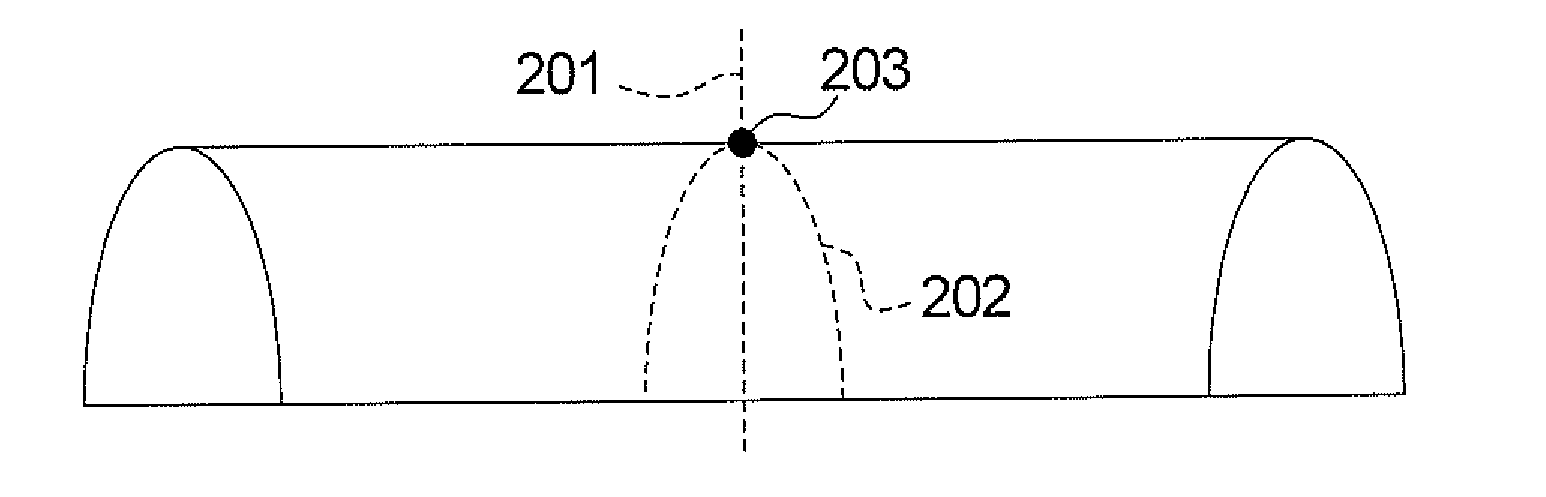
[0019]Aiming at the problems existing in the prior art, the present invention proposes a completely new method for correcting the uniformity of a magnetic field, i.e. by determining how much the shim current in the active shim shell should be set so as to meet the uniformity requirements of the magnetic field according to the actual placement position of the active shim shell (ASS), and setting the shim current in the active shim shell according to the determined result.

[0020]In order to make the technical solution of the present invention more apparent, the solution of the present invention will be further described in detail below by referring to the accompanying drawings and said embodiments.

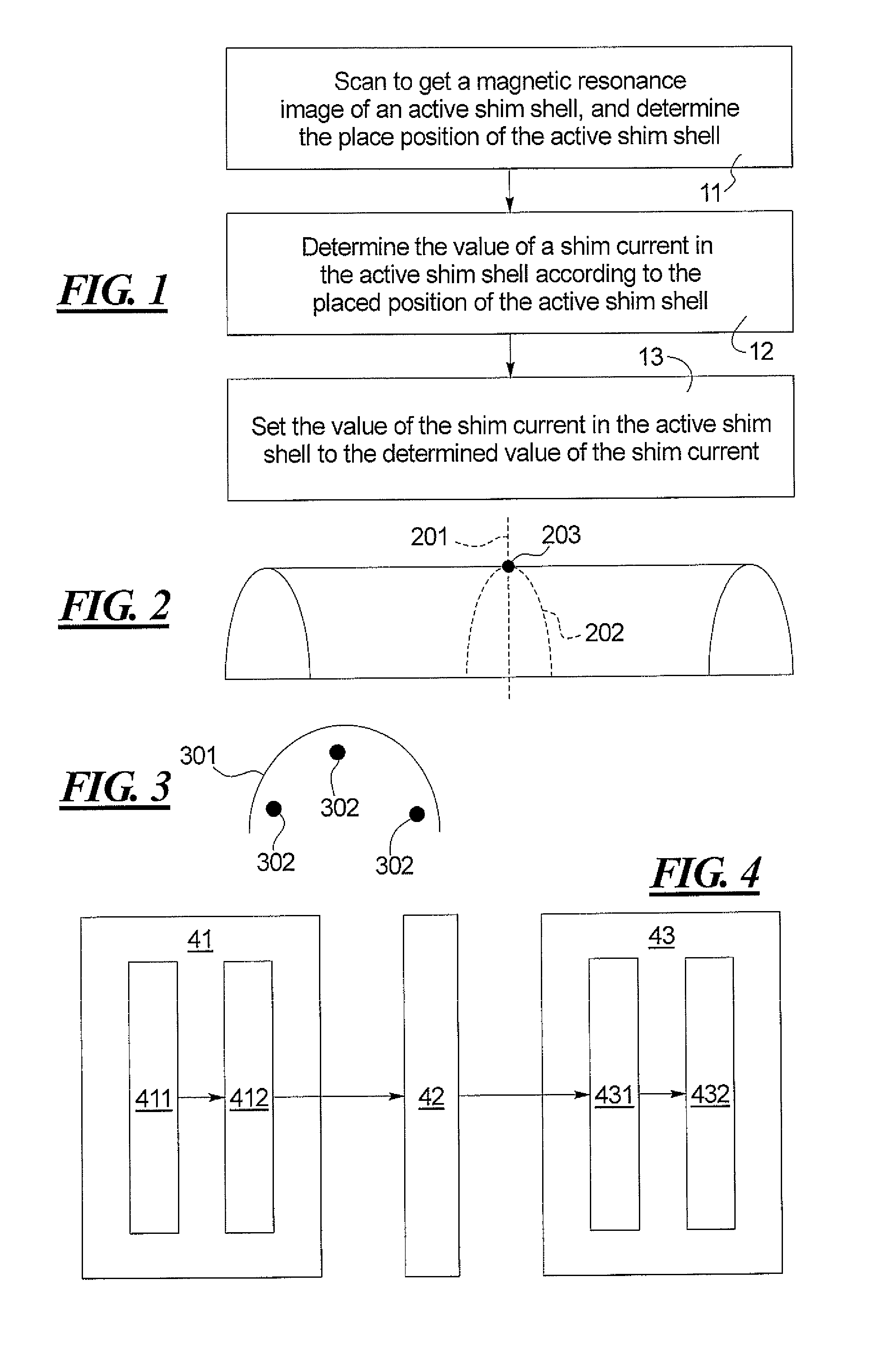
[0021]FIG. 1 is a flow chart of an embodiment of the method for correcting the uniformity of a magnetic field of the present invention. As shown in FIG. 1, it includes the following steps:

[0022]Step 11: placing an active shim shell into the magnetic field, scanning to get a magnetic resonance...


PUM


Abstract

In a method and apparatus for correcting the uniformity of a magnetic field, an active shim shell is placed in the magnetic field, a magnetic resonance image of the active shim shell obtained, and the placement position of the active shim shell is determined by analyzing the magnetic resonance image. The value of a shim current in the active shim shell is determined so as to meet the uniformity requirements of the magnetic field according to the placement position. The value of the shim current in said active shim shell is set to the determined value of the shim current.

Description

BACKGROUND OF THE INVENTION[0001]1. Field of the Invention[0002]The present invention relates to the technology of magnetic resonance (MR) and, particularly, to a method and an apparatus for correcting the uniformity of a magnetic field in a magnetic resonance system.[0003]2. Description of the Prior Art[0004]In current magnetic resonance (MR) systems, in order to obtain a magnetic resonance image with relatively good quality, a relatively high uniformity (homogeneity) of the basic magnetic field is required, the basic magnetic field being generated by a basic field magnet. Generally, there are no problems with the uniformity of the magnetic field in the central area of such a magnet (i.e. an annular area), while the uniformity of the magnetic field will decline significantly in the non-central areas. For acquiring MR data from certain tissues and organs, such as the shoulder or chest, etc., since a patient lies flat on the patient bed, which passes through the magnet, these organs ...

Claims


Application Information

Patent Timeline
Patent Type & Authority Patents(United States)
IPC IPC(8): G01R33/44
CPCG01R33/3875G01R33/58
Inventor CHEN, JIN JUNSCHRECK, OLIVER
Owner SIEMENS HEALTHCARE GMBH
Why Eureka
Try Eureka