
Windshield wiper device

a technology for wiper blades and windows, which is applied in the direction of vehicle maintenance, vehicle cleaning, domestic applications, etc., can solve the problems of wiper blades getting loose from the oscillating arm, high forces being exerted on the connection between the connecting device and the oscillating arm,

Active Publication Date: 2013-09-03
TRICO BELGIUM SA
View PDF7 Cites 26 Cited by
  • Summary
  • Abstract
  • Description
  • Claims
  • Application Information

AI Technical Summary

Benefits of technology

The invention is a windscreen wiper device that connects a connecting device and an oscillating arm using a minimum of parts. The connecting device has two parts that can be detachably connected together using protrusion / hole means. The first part is retained onto the wiper blade and the second part has an U-shaped cross-section at the location of its connection to the first part. Each leg of the U-shaped cross-section is bendable between a first position where the parts are snapped together using a snapping operation and a second position where they are released from each other by sliding the oscillating arm off the second part. The first part may have abutting surfaces for abutting against the legs of the U-shaped cross-section or protrusions that engage with the abutting surfaces. The second part may have a resilient tongue that engages in a correspondingly shaped hole in the oscillating arm. The invention also provides alternative ways of connecting the connecting device to the oscillating arm.

Problems solved by technology

In practice it has become apparent that, during use of the known windscreen wiper device, high forces are exerted on the connection between the connecting device and the oscillating arm.
As a consequence thereof the wiper blade may get loose from the oscillating arm.

Method used


Image

  • Windshield wiper device
  • Windshield wiper device
  • Windshield wiper device

Examples


Embodiment Construction

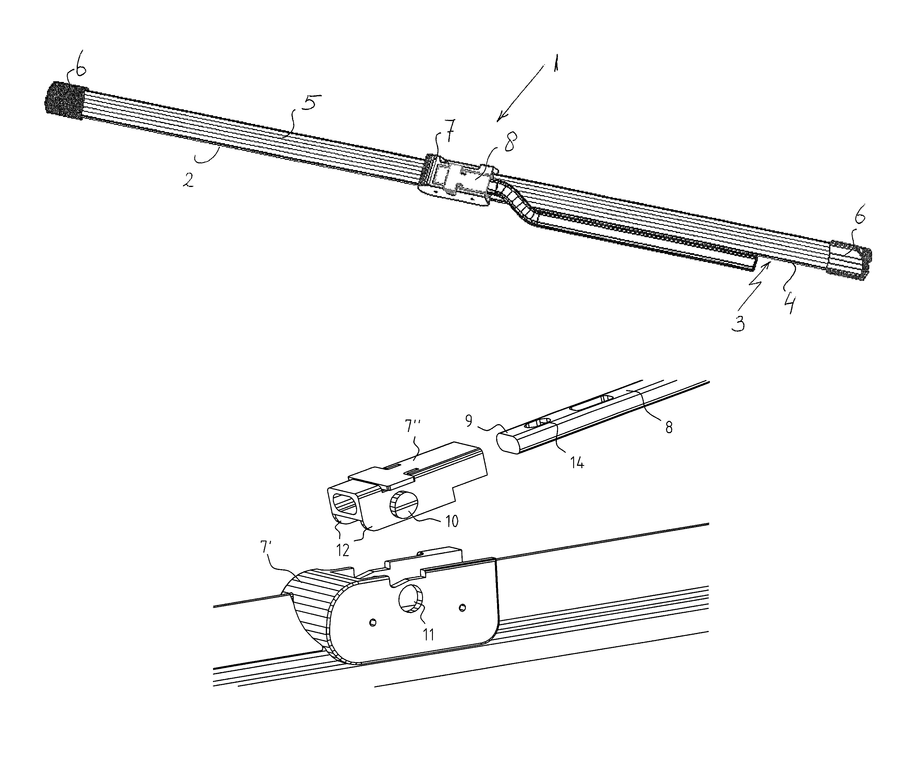
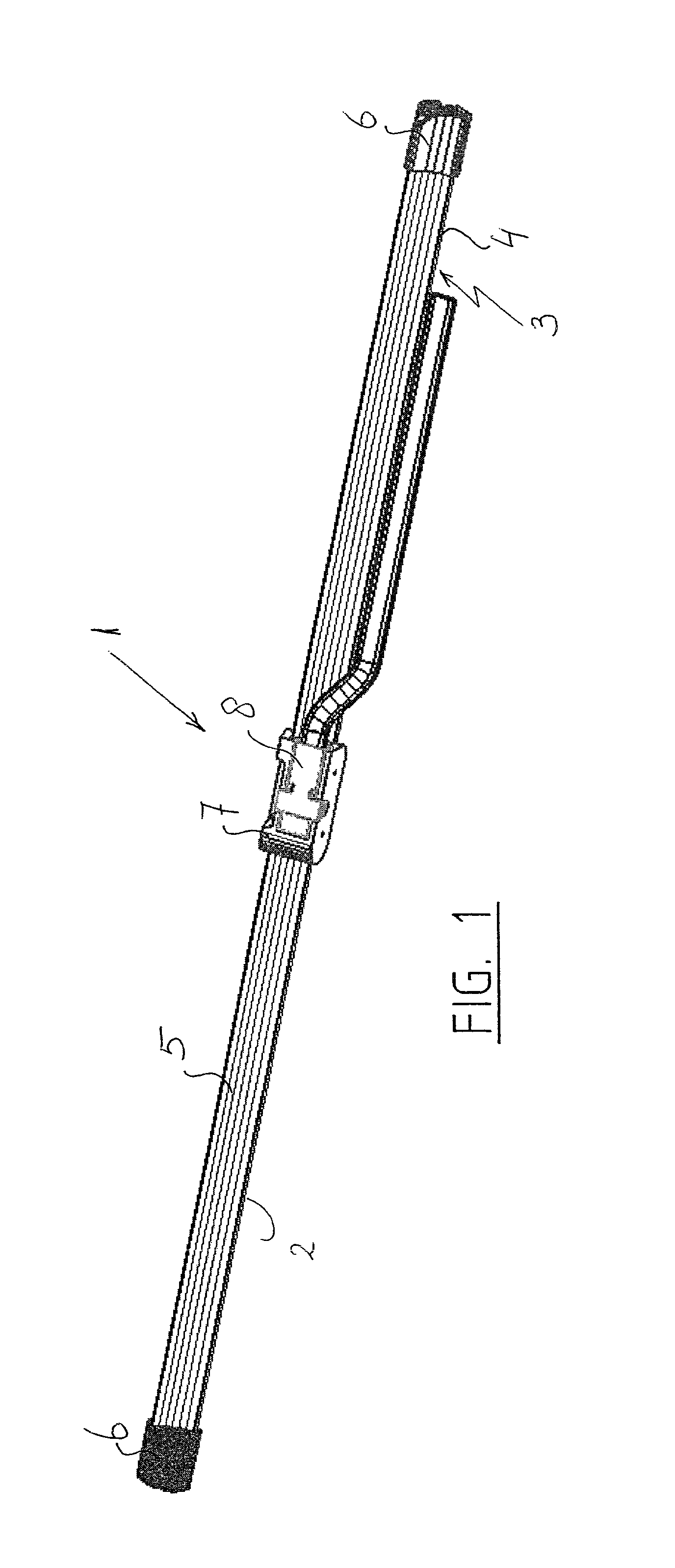
[0023]FIG. 1 shows a windscreen wiper device 1 of the “yokeless” type according to the invention. The windscreen wiper device is built up of an elastomeric wiper blade 2 , in the longitudinal sides of which opposing longitudinal grooves 3 are formed, and of longitudinal strips 4 made of spring band steel, which are fitted in the longitudinal grooves 3. The strips 4 form a flexible carrier element for the rubber wiper blade 2 , as it were, which is thus biased in a curved position (the curvature in operative position being that of a windscreen to be wiped). Neighboring ends of strips 4 are interconnected on either side of the windscreen wiper device 1 by means of connecting pieces 6 functioning as clamping members. In this embodiment, the connecting pieces 6 are separate constructional elements , which may be form-locked ( “positive locking” or “having positive fit”) as well as force-locked to the ends of strips 4. In another preferred variant, the connecting pieces 6 are in one piec...


PUM


Abstract

A windscreen wiper device comprising an elastic, elongated carrier element, as well as an elongated wiper blade of a flexible material, which can be placed in abutment with a windscreen to be wiped, which wiper blade includes opposing longitudinal grooves on its longitudinal sides, in which grooves spaced-apart longitudinal strips of the carrier element are disposed, wherein neighbouring ends of said longitudinal strips are interconnected by a respective connecting piece, which windscreen wiper device comprises a connecting device for an oscillating arm, wherein the oscillating arm is pivotally connected to the connecting device about a pivot axis near one end, with the special feature that the connecting device comprises at least two parts provided with protrusion / hole features for detachably connecting the parts together, wherein the first part is retained onto the wiper blade and wherein the second part has an at least substantially U-shaped cross-section at the location of its connection to said first part, wherein each leg of said U-shaped cross-section is allowed to bend outwardly upon insertion of the oscillating arm into said second part for connecting said first and second parts together through a snapping operation.

Description

BACKGROUND OF THE INVENTION[0001]1. Technical Field[0002]The present invention relates to a windscreen wiper device comprising an elastic, elongated carrier element, as well as an elongated wiper blade of a flexible material, which can be placed in abutment with a windscreen to be wiped, which wiper blade includes opposing longitudinal grooves on its longitudinal sides, in which grooves spaced-apart longitudinal strips of the carrier element are disposed, wherein neighbouring ends of said longitudinal strips are interconnected by a respective connecting piece, which windscreen wiper device comprises a connecting device for an oscillating arm, wherein said oscillating arm is pivotally connected to said connecting device about a pivot axis near one end.[0003]2. Related Art[0004]Such a windscreen wiper device is generally known. This prior art windscreen wiper device is designed as a “yokeless” wiper device, wherein no use is made of several yokes pivotally connected to each other, but...

Claims


Application Information

Patent Timeline
IPC IPC(8): B60S1/40B60S1/34
CPCB60S1/3848B60S1/4038B60S1/40B60S1/4087B60S1/4064B60S1/3849B60S1/4083
Inventor BOLAND, XAVIER
Owner TRICO BELGIUM SA
Features
  • Generate Ideas
  • Intellectual Property
  • Life Sciences
  • Materials
  • Tech Scout
  • Unparalleled Data Quality
  • Higher Quality Content
  • 60% Fewer Hallucinations
Learn More