Collapsible shade device

a shade device and collapsible technology, applied in the field of shade devices, can solve the problem of heavy weight of the shade device, and achieve the effect of reducing the weight of the overall shade devi

Active Publication Date: 2016-11-29
FRIEDMAN STEVE
View PDF36 Cites 8 Cited by
  • Summary
  • Abstract
  • Description
  • Claims
  • Application Information

AI Technical Summary

Benefits of technology

[0008]A first embodiment of the shade device may be set up on a flat generally horizontal surface such as the beach, grass, etc. to provide protection from the harsh sunrays of the sun. When the shade device is set up on the ground, the shade device provides a seat portion upon which the user may sit to protect the user from the dirty ground. The seat portion may be part of a fabric layer that is extended upon a frame of the shade device to block the sun's rays and protect the person sitting on the seat portion from the harmful sunrays. To fold the shade device for easy carry and compact storage, a frame support member is pushed past nubs that hold up the shade device. In particular, the shade device may have two or more frame support members (i.e., collectively, the frame) that are collapsible upon each other. From the erected position, the shade device may be collapsed by an easy push release system. One of the frame support members is held in place by nubs. To initiate the collapse of the shade device, the frame support member is pushed over or past the nubs. After the frame support members are collapsed upon each other, legs of the frame support members are folded inward at joints. The seat portion can be wrapped around the legs and top support members of the frame support members to prevent the legs from unfolding or flopping around during transport, storage, etc. Once the seat portion is wrapped around the legs of the top support members, a strap may be engaged to secure the seat portion around the legs and the top support members. The straps may also have a shoulder strap such that the user may conveniently carry the folded or collapsed shade device on his / her shoulder. The shade device may be fabricated from lightweight material and hollow tubular construction to further reduce the weight of the overall shade device for easy transport (e.g., shoulder carry).
[0009]To erect the shade device, the straps are disengaged. The seat portion is unwrapped from the legs and the top support members. The legs are folded outward at the joints. The frame support members are erected. To this end, the legs or frame support member is pushed over or past nubs. Since a fabric layer which provides the means for protecting the user from the harsh sunrays are attached to the top support members of the frame support members, the fabric layer is extended out when the frame support members are disposed or traversed to the erected position. At the erected position, legs of the frame support member may be held in position by the nubs formed in a bracket that pivotally attaches all of the legs of the frame support members. The shade device requires no additional tools to set up or tear down. The shade device is lightweight due to its construction and minimal parts. It is also intuitive in its set up and tear down.
[0013]To collapse the shade device, the straps, tie downs, or bungee cords are removed from the shade device. The pivoting frame support members are folded toward the central fixed support member. To do so, the pivoting support members are pushed past the nubs. The shade device is removed from the stake bed holes. The legs of the frame support members are pivoted inward. The rear portion of the fabric layer is used to wrap the legs and the top support members of the frame support members. A strap is engaged to secure the rear portion about the legs and the top support members of the frame support member. Shoulder straps are attached to the fabric layer or the securing straps to aid in convenient shoulder carry or transport of the shade device.

Problems solved by technology

The shade device is lightweight due to its construction and minimal parts.

Method used


Image

  • Collapsible shade device
  • Collapsible shade device
  • Collapsible shade device

Examples


Embodiment Construction

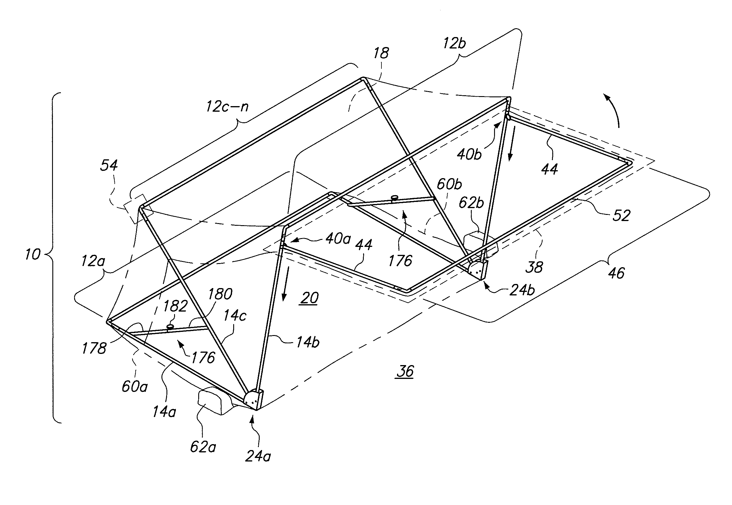
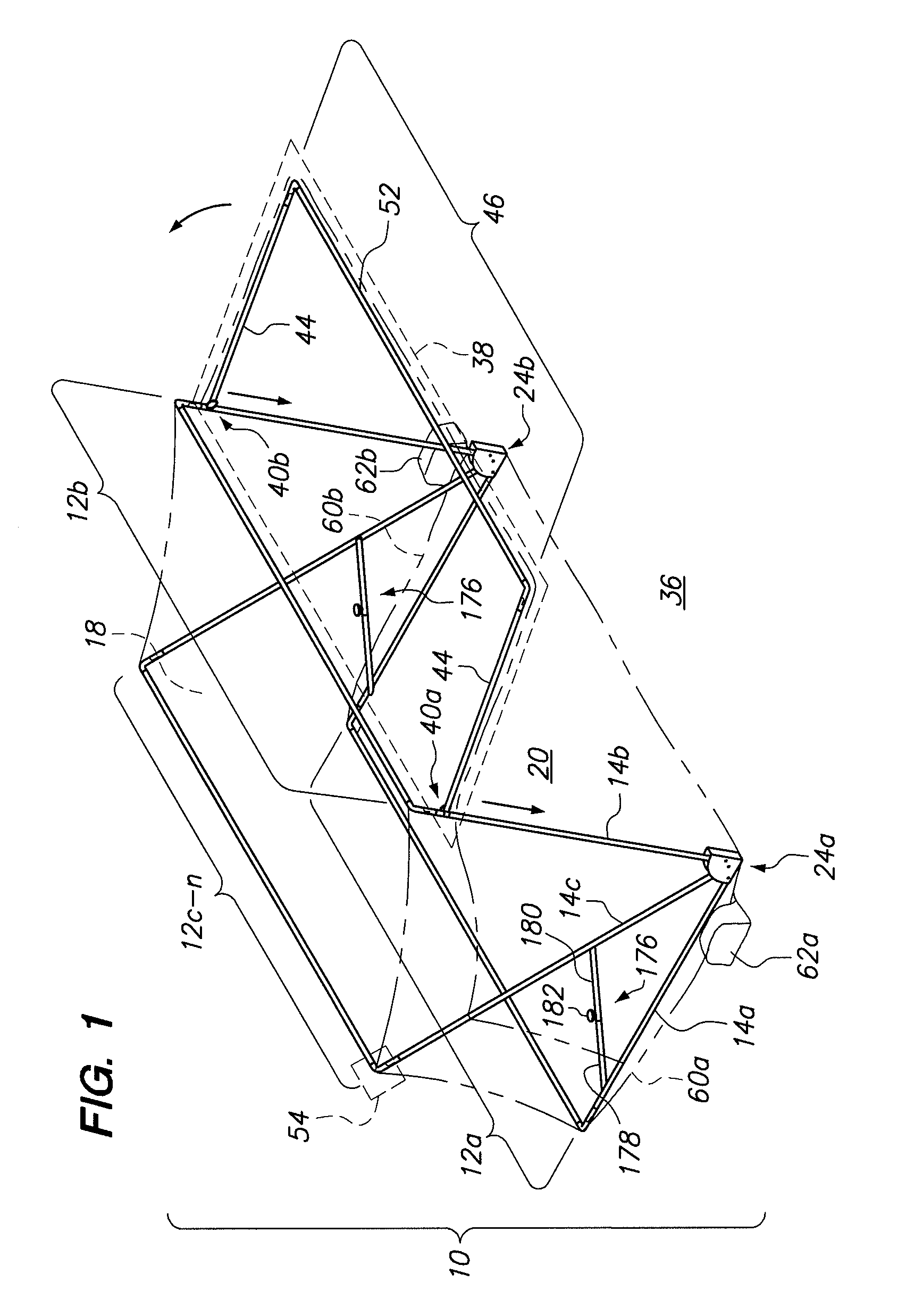
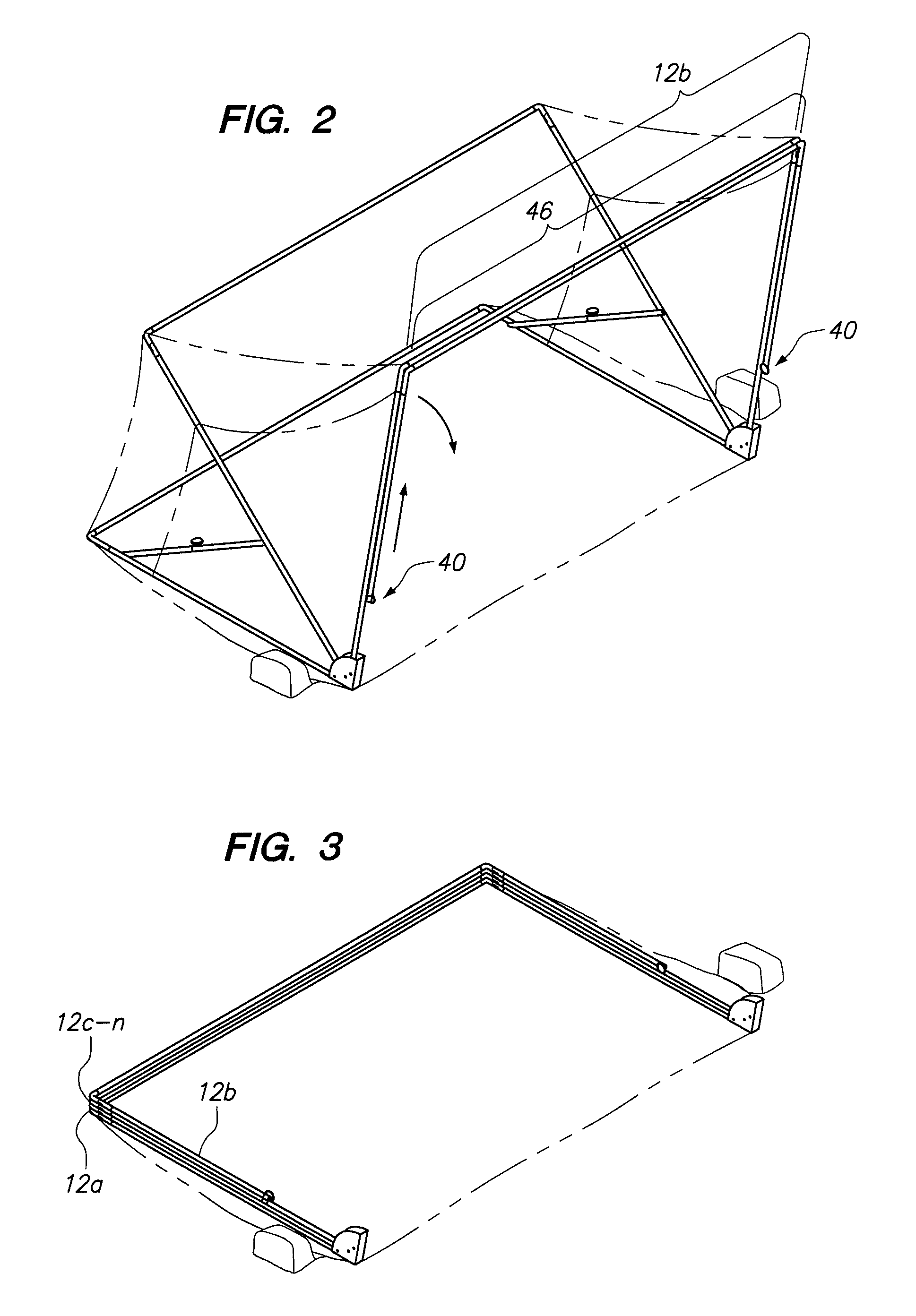
[0068]Referring to the drawings, a collapsible shade device 10 is shown. The collapsible shade device 10 may have a plurality of frame support members 12a-c that are traversable between an erected position (see FIG. 1) and a collapsed position (see FIG. 3). To traverse the frame support members to the collapsed position, one of the frame support members may be held up by nubs as will be discussed below. The frame support member is pushed past the nub to allow the frame support members to be collapsed upon each other. This provides for a simple push release system. Once the frame members 12 are in the collapsed position, legs 14 of the frame support members 12 may be pivoted inward (see FIG. 4) wherein the left and right legs 14 of the frame support members 12 are generally parallel with a top member 16 of the frame support members 12. A fabric layer 18 may be attached to top support members 16 of the frame support members 12 and may be sufficiently long such that the fabric layer 18...


PUM

PropertyMeasurementUnit
angleaaaaaaaaaa
angleaaaaaaaaaa
pivot angleaaaaaaaaaa

Abstract

A shade device for protecting a user from harmful sunrays is provided. The shade device may be held in the erected position with nubs such that to erect the shade device, frame support members are pushed to the erected position. To collapse the shade device, the frame support members are pushed past nubs. Accordingly, the shade device incorporates a simple push release mechanism to erect and collapse the shade device such that no assembly or disassembly of the shade device is required for tear down or set up.

Description

CROSS-REFERENCE TO RELATED APPLICATIONS[0001]This application is a continuation-in-part of U.S. patent application Ser. No. 12 / 640,959, filed Dec. 17, 2009, entitled “Collapsible Shade Device,” the disclosure of which is hereby incorporated by reference herein in its entirety.STATEMENT RE: FEDERALLY SPONSORED RESEARCH / DEVELOPMENT[0002]Not ApplicableBACKGROUND[0003]The present invention relates to a shade device.[0004]In tropical resort areas vacationers seek solitude and isolation from the crowds. Vacationers seek isolated beach areas away from the crowds and modern society in order to relax in a stress free environment. In these isolated areas, the vacationer wants to be shielded or protected from the harmful and harsh sunrays. The sunrays may damage the vacationer's eyes and skin. Sun block and sunglasses may be inadequate since direct contact with the sunrays may cause the person's skin temperature to be elevated beyond a comfortable range. The sunrays may cause the vacationer to...

Claims


Application Information

Patent Timeline
Patent Type & Authority Patents(United States)
IPC IPC(8): E04H15/38E04H15/48E04H15/06E04H15/00
CPCE04H15/38E04H15/003E04H15/06E04H15/48Y10T29/49826E04H15/02E04H15/54E04H15/64F16C11/04
Inventor ARMSTRONG, MICHAELFRIEDMAN, ROBERT
Owner FRIEDMAN STEVE
Why Eureka
Try Eureka