Cycloid rotor engine

a cycloid rotor engine and rotor technology, applied in the field of engines, can solve the problems of difficult sealing of working fluid during compression, engine low efficiency and high emissions, and engine unsuitable for compression ignition mode of operation

Active Publication Date: 2013-09-03
LIQUIDPISTON INC
View PDF96 Cites 43 Cited by
  • Summary
  • Abstract
  • Description
  • Claims
  • Application Information

AI Technical Summary

Benefits of technology

[0025]Another embodiment includes a housing having a working cavity, and a combustion chamber in fluid communication with the working cavity; a piston disposed on the housing and configured to controllably enter into and withdraw from the combustion chamber; a rotor rotatably mounted within the working cavity, so as to form a working chamber of variable volume with the housing, at different angles of rotation of the rotor within the working cavity; and a controller synchronized to the angle of rotation of the rotor to controllably cause the piston to enter into and withdraw from the combustion chamber, so as to cause the combined volume of the working chamber and the combustion chamber to be constant over a range of angles of rotation of the rotor.

Problems solved by technology

The major problem that could be traced to all rotary engines, however, is difficulty in sealing the working fluid during the compression, combustion and expansion strokes of the engines.
While theoretically most of the engines look feasible on paper, since they completely encompass working fluid without using seals, in practice, when machining tolerances and thermal expansion are taken into account and also when parts are starting to wear out, the sealing of working fluid is not possible without seals.
Having said this, it is well known that these engines have relatively low efficiency and high emissions and are unsuitable for compression ignition mode of operation due to:
1. Relatively high degree of leakage, despite the seal grid.
For example, the bouncing of fast-moving apex seals, as well as holes into the engine to accommodate spark plug(s), contribute to leakage.
3. High thermal losses caused by very high surface to volume ratio of the combustion chamber at the moment of highest compression.
5. Necessity to meter oil into the working chamber to lubricate the apex seals, which can't get lubrication by any other means, and the existence of ports through which this oil is exhausted, causing emission problems.
In practice, as stated above, manufacturing tolerances and thermal expansion cause designers to leave a relatively large gap between the rotor and the housing or rotor and rollers.
If housing and rotor are inflexible or if rollers can't accommodate for the thermal expansion or the preload due to machining tolerance, the sealing can't be accomplished.
So, it becomes meaningless to talk about purely rolling contact between rotor and the housing.

Method used


Image

  • Cycloid rotor engine
  • Cycloid rotor engine
  • Cycloid rotor engine

Examples


Embodiment Construction

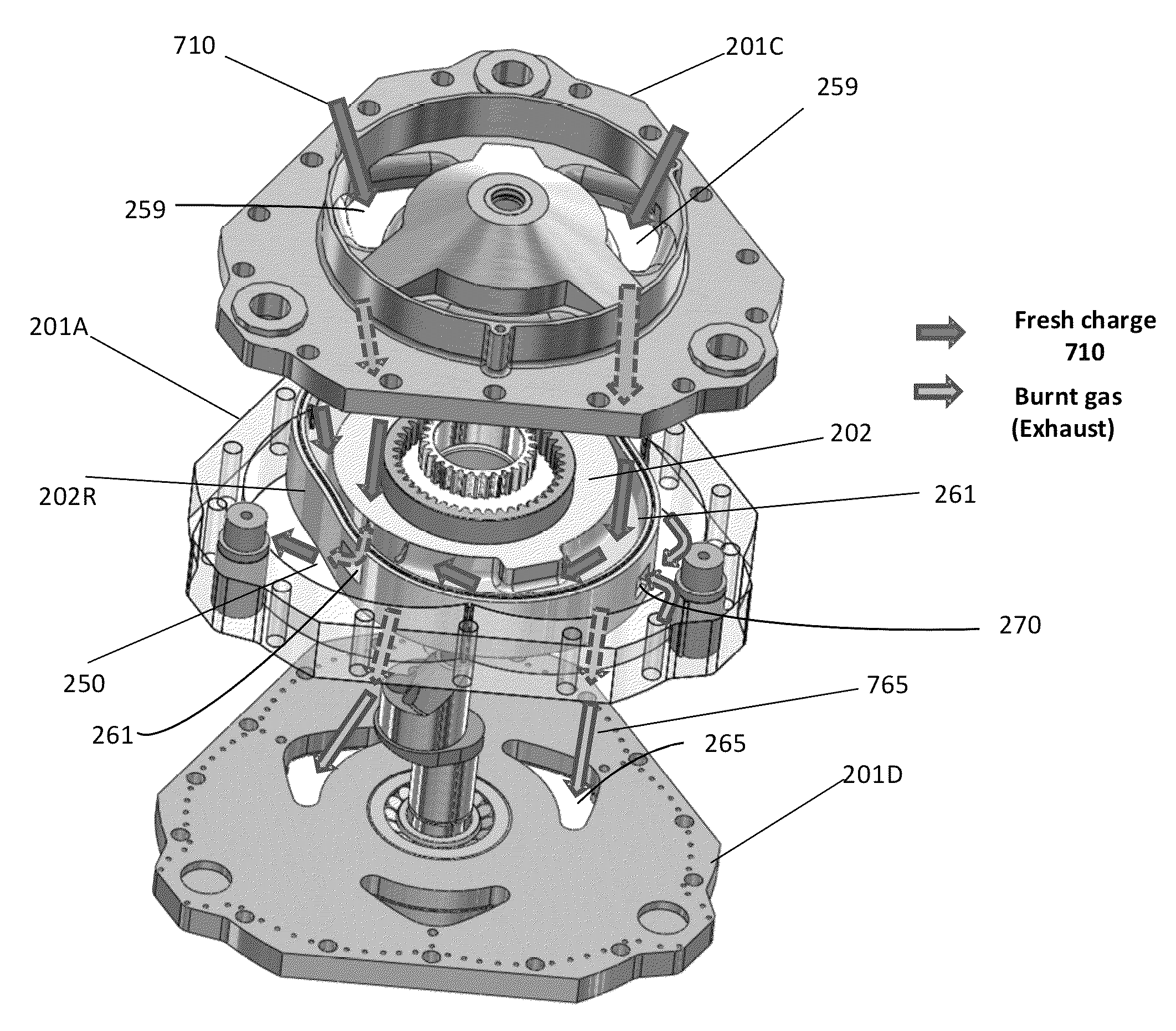
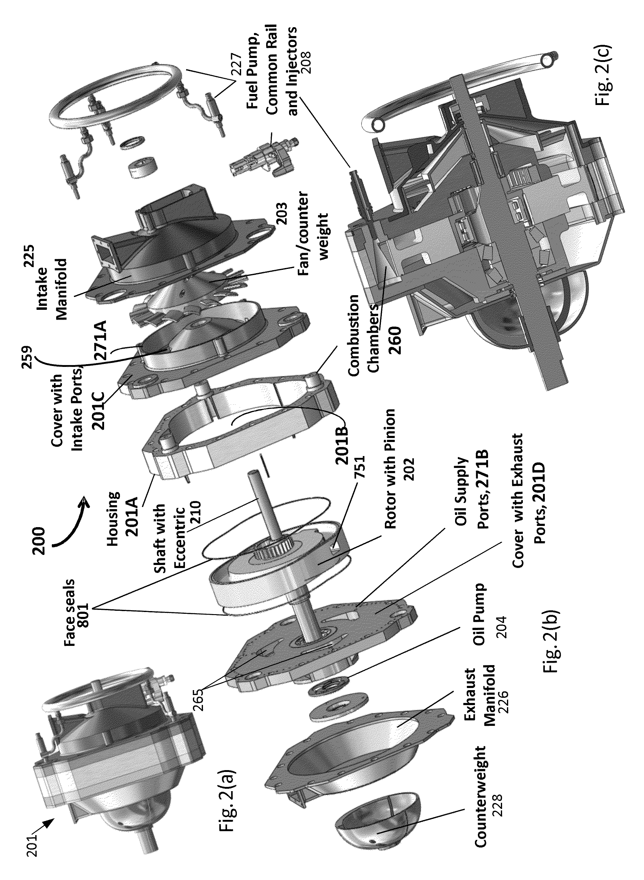
[0011]In a first embodiment of the invention there is provided an improved engine of the type including a cycloidal rotor having N lobes and a housing having a corresponding set of N+1 lobe-receiving regions for successively receiving the lobes as the rotor rotates about an axis relative to the housing, the housing having (i) a pair of sides axially disposed on first and second sides of the rotor, and (ii) a peak disposed between each pair of adjacent lobe-receiving regions, and (iii) an intake port and an exhaust port, wherein the improvement is defined by: a plurality of peak seals, at least one of the plurality of peak seals disposed on each peak and configured to maintain contact with the rotor throughout a period of rotation of the rotor, each seal being radially biased against the rotor throughout the rotation of the rotor, on account of the cycloidal geometry of the rotor and the lobe-receiving portions; a first passageway defined in the rotor to communicate cyclically betwee...


PUM


Abstract

A rotary engine has a cycloid rotor and a sealing grid including a face seal that rotates with the rotor, and including other seals that do not rotate with the rotor. As the rotor rotates within a housing, the rotor, housing and seal grid form at least one working chamber between them, the chamber undergoing a change from initial volume V1 to V2, which is less than V1, thus compressing a working medium, and subsequently expanding to volume V3, which may be larger than V1, such that the chamber volume is a smooth and continuous function of rotor's rotational angle.

Description

PRIORITY[0001]This patent application is a continuation application of U.S. patent application Ser. No. 13 / 434,827 filed Mar. 29, 2012, entitled “Cycloid Rotor Engine” and naming Nikolay Shkolnik and Alexander C. Shkolnik as inventors, and claims priority therefrom, and from provisional U.S. patent application No. 61 / 469,009, filed Mar. 29, 2011, entitled, “Cycloid Rotor Engine” and naming Nikolay Shkolnik and Alexander C. Shkolnik as inventors, the disclosures of which are incorporated herein, in its entirety, by reference.TECHNICAL FIELD[0002]The present invention relates to engines, and more particularly to rotary engines.BACKGROUND ART[0003]Rotary engines have promise of high efficiencies, high power densities and low part count, which have attracted numerous engineers and efforts to this filed. Among great many configurations existing in the prior art, one of the simplest and the most promising is based on the gerotor concept. With reference to FIGS. 1(a)-1(d), depicting prior ...

Claims


Application Information

Patent Timeline
Patent Type & Authority Patents(United States)
IPC IPC(8): F03C2/00F04C2/00
CPCF01C1/22F01C21/04F01C19/085F01C19/005F02B2053/005Y02T10/12F01C19/00F01C1/04F01C19/08F01C21/008F01C21/08F01C21/106F02B53/00
Inventor SHKOLNIK, NIKOLAYSHKOLNIK, ALEXANDER C.
Owner LIQUIDPISTON INC
Why Eureka
Try Eureka