Combination structure for a labyrinth

a labyrinth and combination structure technology, applied in the field of labyrinths, can solve the problems of losing the pleasure and challenge of playing in the labyrinth, taking a long time, and the structure of the labyrinth is deserted, and achieves the effect of convenient assembly and disassembly, and convenient disassembly

Inactive Publication Date: 2013-09-03
CHEN CHIA CHERN
View PDF3 Cites 1 Cited by
  • Summary
  • Abstract
  • Description
  • Claims
  • Application Information

AI Technical Summary

Benefits of technology

[0005]This invention is devised to offer a combination structure for a labyrinth, convenient in assembly and disassembly, applicable to any site, easy to be detached and recombined at will to make up a new labyrinth with different routes, diversified in labyrinth play and safety in use.

Problems solved by technology

The firm joint members of the conventional labyrinth structure are generally screws or iron nails, and the routes designed for the conventional labyrinth are fixed, impossible to be changed at will, and after played for several times, the fixed routes of the conventional labyrinth have been already memorized by the players and become familiar to them, thus losing pleasure and challenge of play in the labyrinth and failing to arouse public interest and in consequence, leaving the labyrinth structure deserted.
Therefore, the labyrinth routes have to be changed frequently for continuously maintaining novelty of the labyrinth play; nevertheless, detaching the components of the labyrinth and then reassembling them together to set up a new labyrinth will take much time and require lots of troubles and in the course of detachment, the separating plates are apt to be damaged and impossible to be reused, not only wasting materials but also contaminating the environment as well.
Further, the fixed type labyrinth components are extremely huge in volume, which are not easy to be moved about and will take too much space in transportation.
Furthermore, after being assembled to make a labyrinth, the separating plates are in a closed condition and hence, the moving directions of the players in the labyrinth cannot be seen from the outside.
Thus, when children are playing in the labyrinth, parents are unable to know where the children are, and the children inside the labyrinth may begin to cry because of panic and even worse, danger may occur to the children.

Method used


Image

  • Combination structure for a labyrinth
  • Combination structure for a labyrinth
  • Combination structure for a labyrinth

Examples


Embodiment Construction

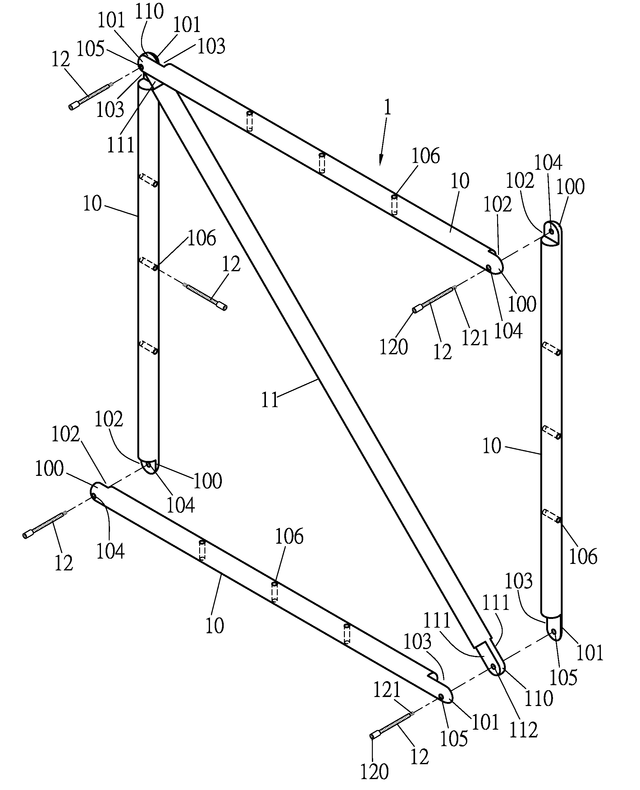
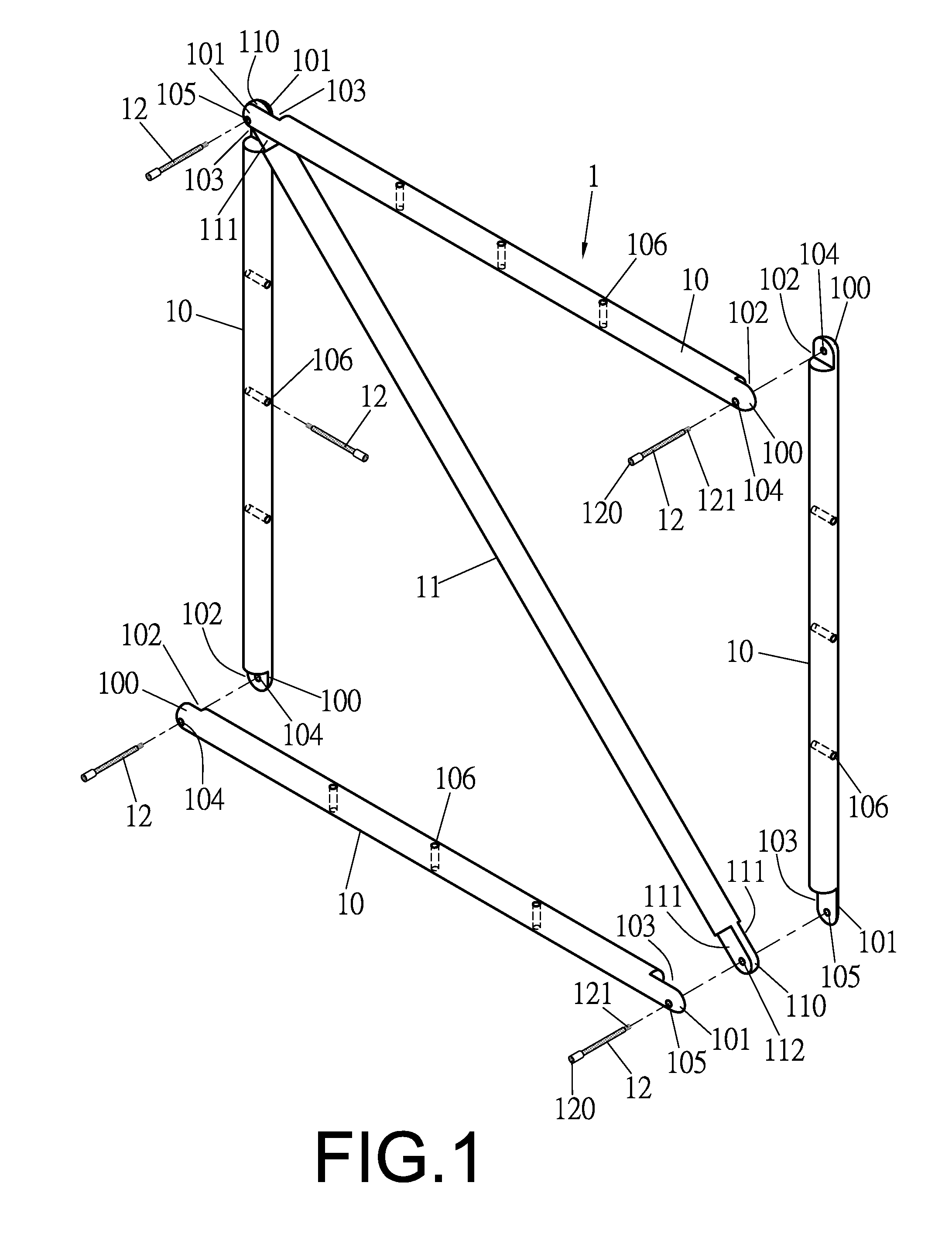
[0019]A preferred embodiment of a combination structure for a labyrinth in the present invention, as shown in FIGS. 1-3, includes several labyrinth units 1 combined together, and each labyrinth unit 1 is composed of four frame rods 10, a reinforcing support bar 11 and a plurality of fixing members 12.

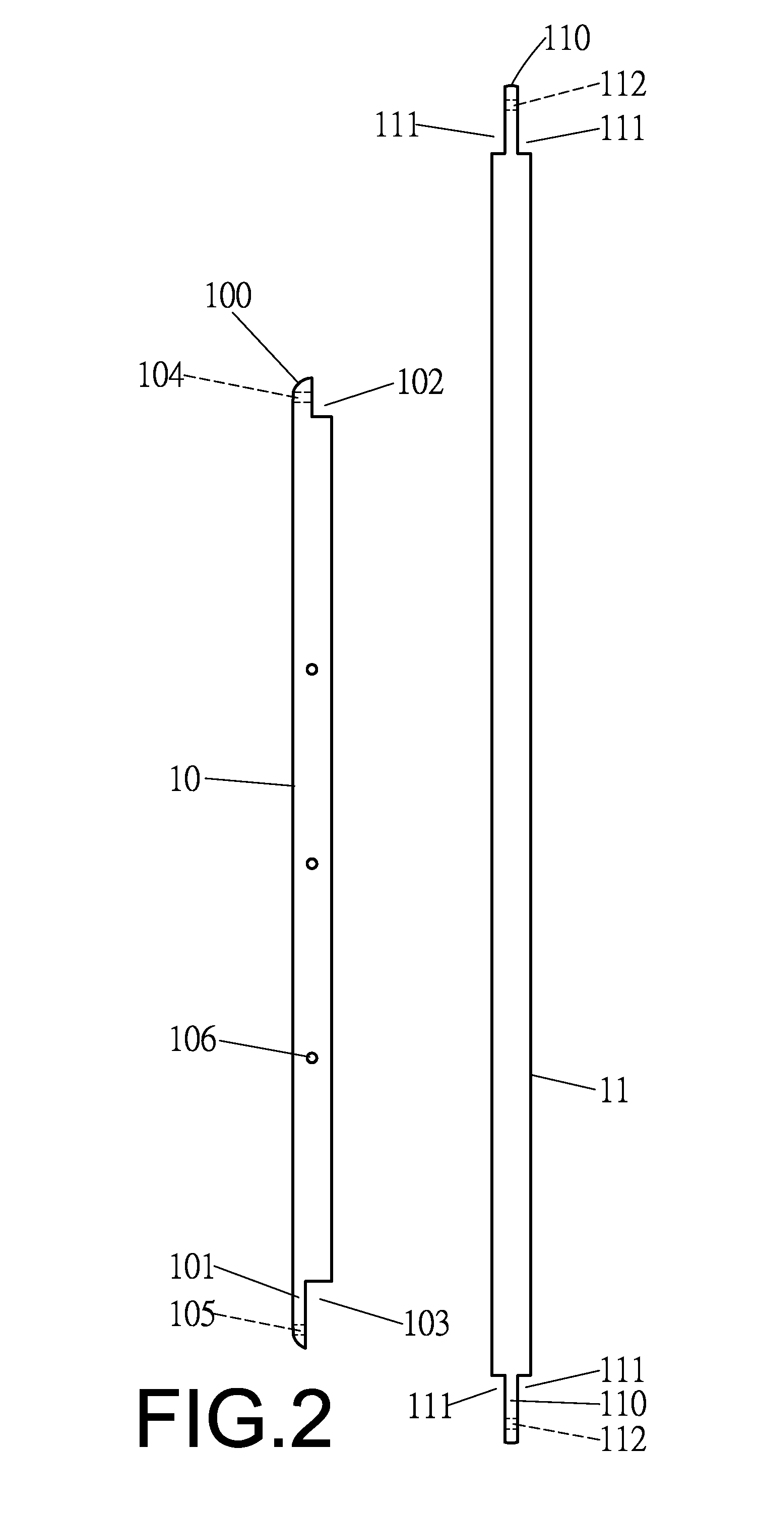
[0020]The four frame rods 10 are vertically butt jointed and formed into a square, and each frame rod 10 has two ends respectively provided with a connecting end 100, 101. The connecting end 100 is axially cut with a one-half recess 102 and bored with an insert hole 104, while another connecting end 101 is axially cut with a two-thirds recess 103 and disposed with an insert hole 105, and each frame rod 10 has its wall provided with a plurality of insert holes 106.

[0021]The reinforcing support bar 11 is to be obliquely set inside the four frame rods 10 and has two ends respectively formed into a connecting end 110, which is bored with an insert hole 112 and has two sides respectively and...


PUM


Abstract

A combination structure for a labyrinth includes plural labyrinth units, which are combined into various labyrinths, respectively composed of four frame rods, a reinforcing support bar and plural fixing members. The four frame rods have their ends butt jointed to form into a square, each frame rod is formed with two connecting ends respectively cut with a recess and provided with an insert hole and each having its wall bored with plural insert holes. The reinforcing support bar is obliquely set inside the four frame rods and formed with two connecting ends respectively bored with an insert hole and having two sides respectively cut with a lengthwise recess. The fixing members are inserted in the insert holes of the connecting ends of the four frame rods and of the reinforcing support bar for securing the four frame rods and the reinforcing support bar together to form a labyrinth unit.

Description

BACKGROUND OF THE INVENTION[0001]1. Field of the Invention[0002]This invention relates to a combination structure for a labyrinth, particularly to one that is convenient to be assembled, disassembled and transported and can be changed and recombined to form different routes as one pleases, diversified in labyrinth play, safe in use and able to attain an effect of implying instruction in amusement.[0003]2. Description of the Prior Art[0004]Generally, a conventional labyrinth structure sets up outdoors for amusement or for teaching includes several separating plates and firm joint members combined together. The firm joint members of the conventional labyrinth structure are generally screws or iron nails, and the routes designed for the conventional labyrinth are fixed, impossible to be changed at will, and after played for several times, the fixed routes of the conventional labyrinth have been already memorized by the players and become familiar to them, thus losing pleasure and chall...

Claims


Application Information

Patent Timeline
Patent Type & Authority Patents(United States)
IPC IPC(8): A63J11/00
CPCA63H33/008A63J11/00
Inventor CHEN, CHIA-CHERN
Owner CHEN CHIA CHERN
Why Eureka
Try Eureka