Method and apparatus for improved cutting life of a plasma arc torch

Active Publication Date: 2013-09-03
HYPERTHERM INC
View PDF21 Cites 25 Cited by
  • Summary
  • Abstract
  • Description
  • Claims
  • Application Information

AI Technical Summary

Benefits of technology

[0008]The present invention achieves these objectives by configuring an insert within a cavity of an electrode that allows for substantial and controlled movement of the insert during operation and/or thermal cycling of the torch, so that the degradation of the insert during ther

Problems solved by technology

In all plasma arc torches, particularly those using a reactive plasma gas, the electrode shows wear over time in the form of a generally concave pit at the exposed emission surface of the insert.
During the operation of plasma arc torch electrodes, torch conditions such as temperature gradients and dynamics work to reduce the ret

Method used


Image

  • Method and apparatus for improved cutting life of a plasma arc torch
  • Method and apparatus for improved cutting life of a plasma arc torch
  • Method and apparatus for improved cutting life of a plasma arc torch

Examples


Example

DETAILED DESCRIPTION OF THE DRAWINGS

[0039]Reference will now be made in detail to embodiments of the invention, one or more examples of which are illustrated in the figures. Each embodiment described or illustrated herein is presented for purposes of explanation of the invention, and not as a limitation of the invention. For example, features illustrated or described as part of one embodiment can be used with another embodiment to yield still a further embodiment. It is intended that the present invention include these and other modifications and variations as further embodiments.

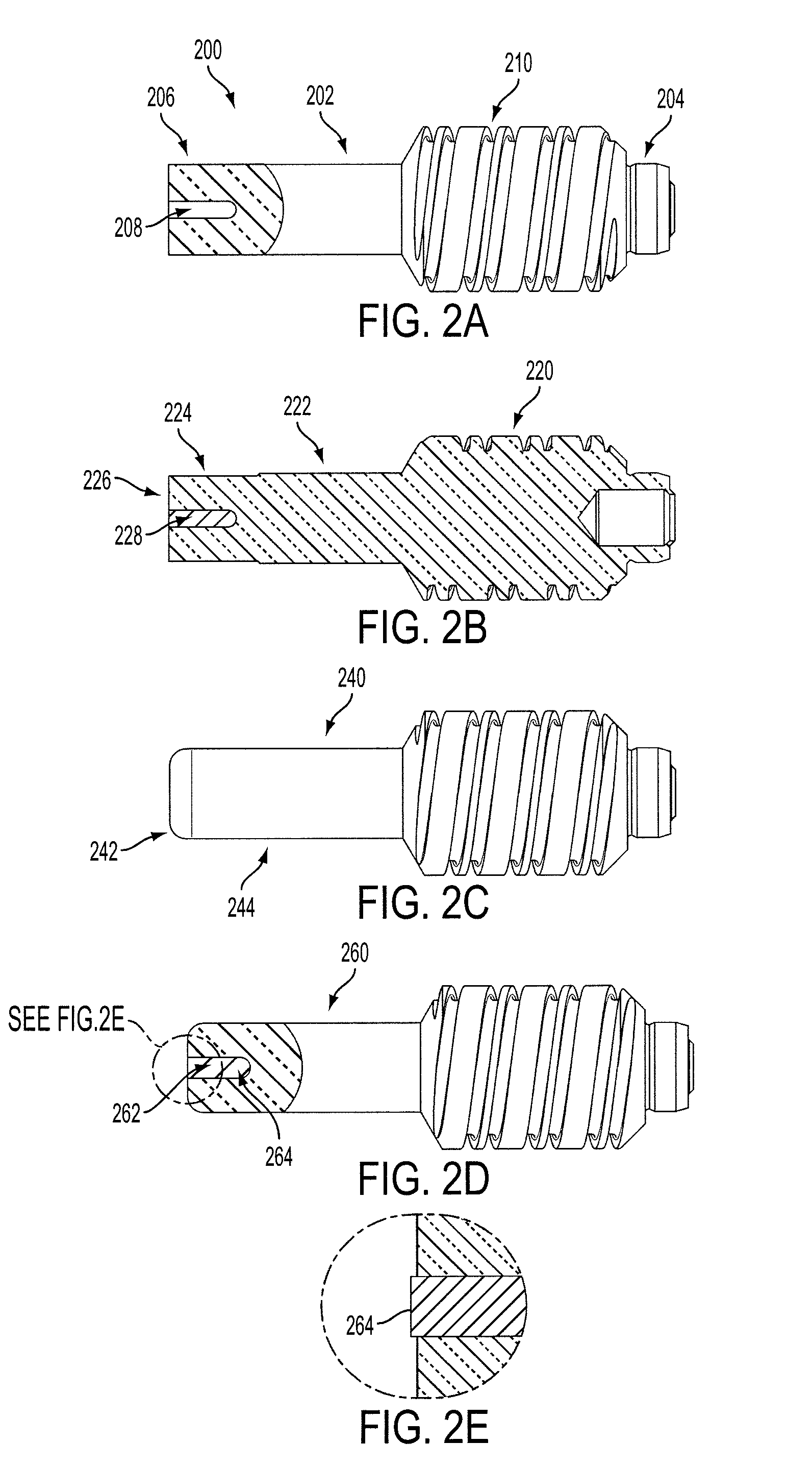
[0040]FIGS. 2A-2E illustrate an exemplary method for securing an insert into an electrode cavity and depict the resulting electrode configuration incorporating principles of the present invention. FIG. 2A illustrates an initial configuration of an electrode 200 comprising an electrode body 202 having a first end 206 and a second end 204 that is opposite the first end 206. An orifice 208 can be formed at the...


PUM

PropertyMeasurementUnit
Lengthaaaaaaaaaa
Lengthaaaaaaaaaa
Lengthaaaaaaaaaa

Abstract

An improved electrode for use in a plasma arc torch. The electrode includes an electrode body, a cavity in a front face at a first end of the electrode body, and an insert disposed in the cavity. The first end of the electrode body is formed of high purity copper containing at least 99.81% copper. The insert has a first end and a second end and is formed of a high emissivity material. A diameter of the first end of the insert is less than a diameter of a second end of the insert. An electrode is compressed to retain the insert using radial compression. The invention also includes a method for forming the electrode, and a method of operation of an electrode in a plasma torch.

Description

FIELD OF THE INVENTION[0001]The invention generally relates to the field of plasma arc torch systems and processes. More specifically, the invention relates to improved insert configurations in electrodes for use in a plasma arc torch, and methods of operation and manufacturing such electrodes.BACKGROUND[0002]Plasma arc torches are widely used in the high temperature processing (e.g., cutting, welding, and marking) of metallic materials. As shown in FIG. 1A, a plasma arc torch generally includes a torch body 1, an electrode 2 mounted within the body, an insert 3 disposed within a bore of the electrode 2, a nozzle 4 with a central exit orifice, a shield 5, electrical connections (not shown), passages for cooling and arc control fluids, a swirl ring to control the fluid flow patterns, and a power supply (not shown). The torch produces a plasma arc, which is a constricted ionized jet of a plasma gas with high temperature and high momentum. A gas can be non-reactive, e.g. nitrogen or ar...

Claims


Application Information

Patent Timeline
IPC IPC(8): B23K9/02B23K9/00B23K9/24B23K26/06H01J17/26H01J7/24
CPCH05H1/34B23K10/00H05H1/28H05H1/3405H05H1/46B23K11/3009H05H2001/3442Y10T29/49117H05H1/3442
Inventor MATHER, JONATHAN P.TWAROG, PETER J.
Owner HYPERTHERM INC
Why Eureka
Try Eureka