Network operation management system

a network operation management and network relay technology, applied in the field of network relay apparatus management, can solve the problems of inability to apply the system to the network, inability to provide spare routers for substitution for a plurality of routers, and long time and effort for setting each router and server

Active Publication Date: 2013-09-03
ALAXALA NETWORKS
View PDF12 Cites 11 Cited by
  • Summary
  • Abstract
  • Description
  • Claims
  • Application Information

AI Technical Summary

Benefits of technology

[0013]It is therefore an object of the present invention to provide techniques for operating and managing a plurality of network relay apparatuses in an overall network with physical connection information associated with positional information, and setting a complicated configuration definition for a network relay apparatus at the time the network relay apparatus is connected to another network relay apparatus or a network management apparatus, such that a fault or a change is detected when it occurs to reflect differences to the physical connection information and positional information, thereby appropriately setting the respective apparatus.
[0014]It is another object of the present invention to provide techniques for allowing a plurality of network relay apparatuses to communicate with adjacent apparatuses to sequentially set a configuration definition to the network relay apparatus in order from a network relay apparatus which is connected to a network management apparatus, thereby making it possible to set the configuration definition to a network relay apparatus which is not located at a gateway.
[0023]Thus, when the network relay apparatus fails in the network, or when a link is disconnected for some case, the network relay apparatus or link at a fault location is replaced with the same type of apparatus or link, and the replaced apparatus or link is properly wired in a range in which an adjacent relationship between apparatuses is maintained, thus making it possible to facilitate apparatus replacement operations upon occurrence of a fault by comprising the steps of:

Problems solved by technology

However, the system described in JP-A-2004-193988 assumes that there has previously existed a network which is capable of communicating with external networks through IP packets and is provided with gateway routers, so that the system cannot be applied to a network which is not connected to external networks, or a network which is to be built from the beginning, because of the inability to communicate with an initial server.
Also, since a router identifier must be used without fail, long time and effort is required for setting each router and server and replacing a failed router with a normal one, and routers can be installed only at limited locations.
Further, since the router identifier must be taken into account at all times, spare routers cannot be provided for substitution for a plurality of routers such that a failed router is immediately replaced with a spare router.
Actually, however, there are many opportunities of additionally installing network relay apparatuses in a network and changing the settings therefor because a so far operative network relay apparatus fails and must therefore be replaced with an alternative apparatus, or a network design must be modified due to an increase or a decrease in capacity.
When an actual network is set in a network relay apparatus, it is difficult for an engineer or an operator to manually perform similar settings in an appropriate manner, particularly for the same type or similar types of a plurality of network relay apparatuses, and erroneous inputs and erroneous connections are difficult to find during an analysis on a fault.
Also, modifications are erroneously reflected to network specifications in many cases, resulting in an increase in cost when a network relay apparatus is introduced or changed.

Method used


Image

  • Network operation management system
  • Network operation management system
  • Network operation management system

Examples


first embodiment

1.

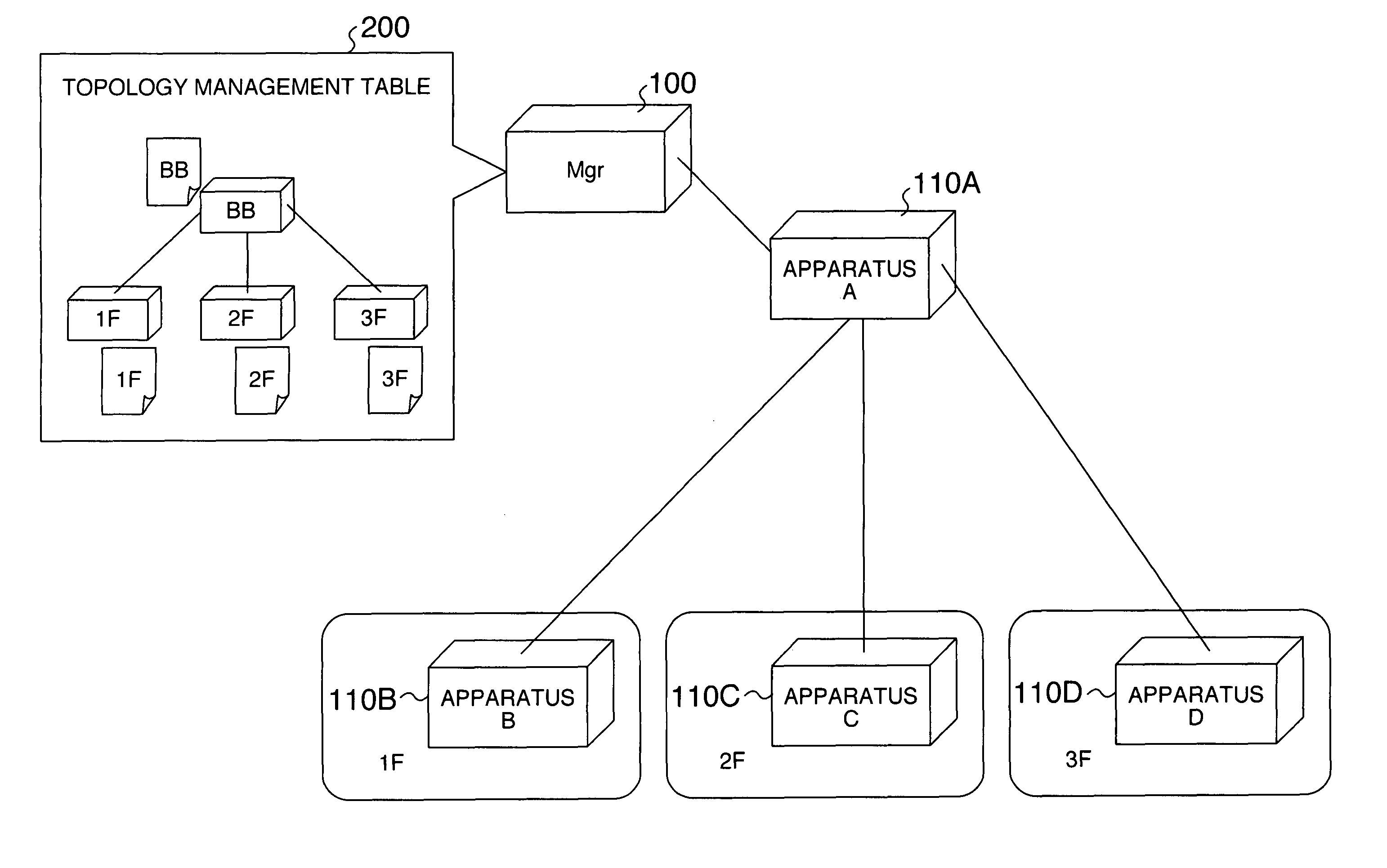
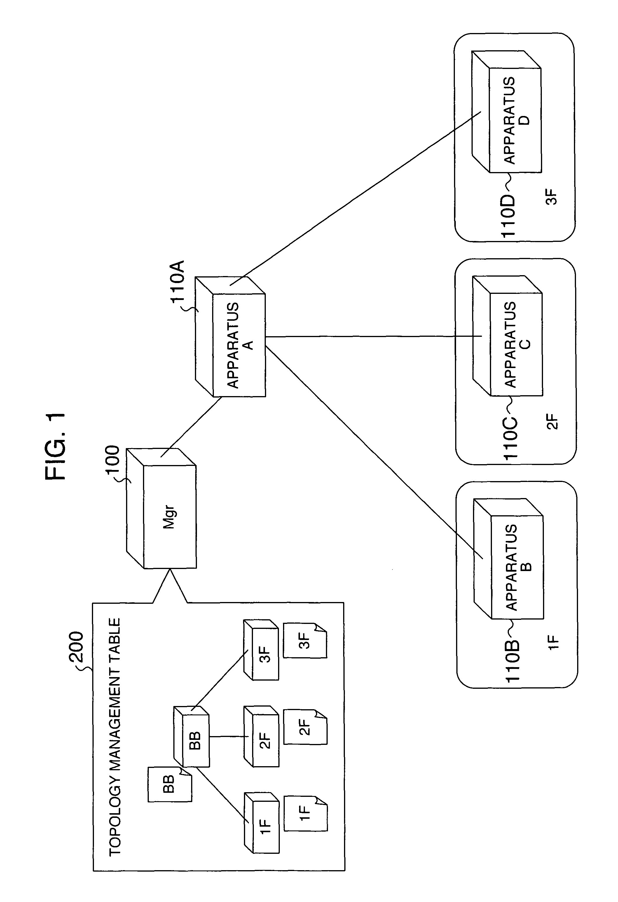
[0068]FIG. 1 illustrates the configuration of a network operation management system. The system includes a network management apparatus (hereinafter sometimes abbreviated as Mgr) 100; network relay apparatuses 110A-110D, hereinafter simply called apparatus A, apparatus B, apparatus C, and apparatus D, respectively; and an imaged topology management table 200 which is managed by the network management apparatus 100 in a tabular

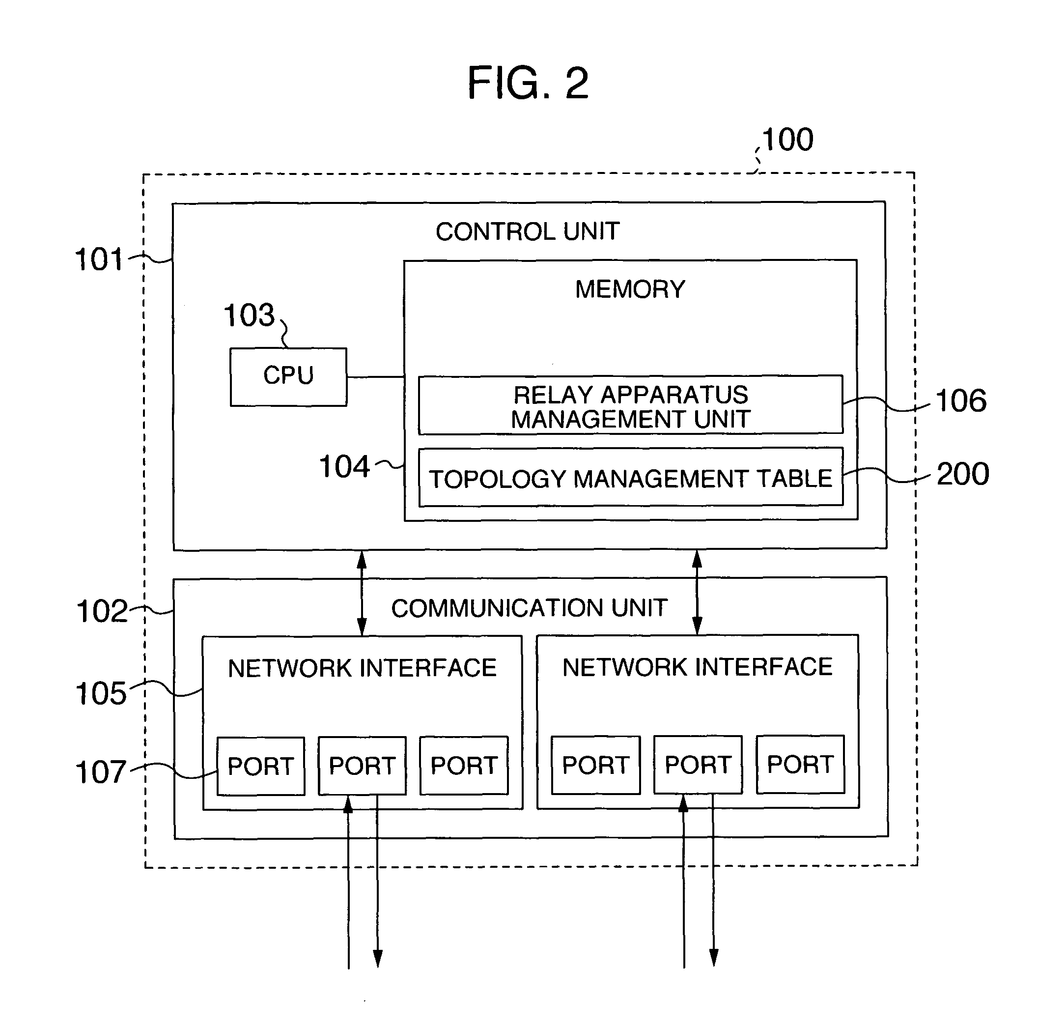
[0069]FIG. 2 illustrates a block diagram of the network management apparatus (Mgr) 100. The network management apparatus 100 includes a control unit 101 and a communication unit 102. The control unit 101 includes a CPU 103, a memory 104, and a table, later described, for executing sequences, later described (the control unit 101 is also called a positional information determination unit, a configuration definition information comparison unit, and a path priority management unit). The communication unit 102 comprises one or a plurality of network interfaces 10...

second embodiment

4.

[0113]A second embodiment provides a redundant configuration, where links are established not only between apparatus A and apparatus D but also between apparatus C and apparatus D in the first embodiment, so that apparatus D has a plurality of parent paths. FIG. 15 illustrates a network topology when there are two parent paths in the adjacent apparatus management table of apparatus D, and FIG. 16 illustrates a sequence for recognizing a second parent path. A timing at which apparatus C is connected to apparatus D may be after apparatus D has started and has been assigned the location 3F by way of apparatus A or during the starting process of apparatus D because the network management apparatus regards a path from apparatus A as a parent path. Therefore, assume in FIG. 16 that apparatus C is connected to apparatus D after the starting process.

[0114]When a connection is made between apparatus C and apparatus D (S341), an adjacent / Mgr detection message is transmitted from apparatus C...


PUM


Abstract

A network management apparatus is previously registered with a physical connection relationship and positional information of a plurality of network relay apparatuses which form part of a network, as well as a configuration definition corresponding to the positional information, such that the network management apparatus can initially detect network relay apparatuses connected to the network management apparatus, and distribute a configuration definition, which takes into account a connection relationship, to the network relay apparatuses connected thereto to set the configuration definition in the network relay apparatuses in order. In this way, even if wiring is freely made, the configuration definition which should be set in each network relay apparatus can be appropriately distributed to and set in one adjacent network relay apparatus to another. Upon occurrence of a fault, the network can be appropriately recovered by a previously set recovering scheme.

Description

INCORPORATION BY REFERENCE[0001]The present application claims priority from Japanese application JP2005-291902 filed on Oct. 5, 2005, the content of which is hereby incorporated by reference into this application.BACKGROUND OF THE INVENTION[0002]1. Field of the Invention[0003]The present invention relates to technologies for managing a network relay apparatus in a network operation.[0004]2. Description of the Related Art[0005]In a conventional network operation, network relay apparatuses are monitored in accordance with SNMP (A Simple Network Management Protocol) defined by RFC (Request For Comments) 1067 published by IETF (The Internet Engineering Task Force) to notify a network manager of a fault such as a disconnection of a link, if any, by SNMP, prompting the network manager to deal with the fault. There are few SNMP-based setting changing means.[0006]Also, means for setting configuration data into a network relay apparatus uses Telnet defined by RFC854 and HTTP (Hypertext Tran...

Claims


Application Information

Patent Timeline
Patent Type & Authority Patents(United States)
IPC IPC(8): G06F15/173H04L12/70H04L12/701H04L12/721
CPCH04L41/0816H04L41/12
Inventor KITANI, MAKOTOMIYAMOTO, TAKAHISA
Owner ALAXALA NETWORKS
Why Eureka
Try Eureka