Display device with luminance variation control unit

a control unit and display device technology, applied in the field of display devices, to achieve the effect of reducing flicker, excellent quality, and reducing luminan

Active Publication Date: 2013-09-10
PANASONIC LIQUID CRYSTAL DISPLAY CO LTD +1
View PDF11 Cites 4 Cited by
  • Summary
  • Abstract
  • Description
  • Claims
  • Application Information

AI Technical Summary

Benefits of technology

[0010]Under the circumstances, the inventors of the present invention have made a study on a method of controlling LEDs so as to avoid flicker even in displaying a moving image. In the course of the study, the inventors have discovered that flicker becomes more noticeable in a display where an object in the video moves at lower velocity (for example, a display in which the foreground scrolls at lower velocity), while luminance substantially reduces in a display in which an object in the video moves at higher velocity (for example, a display in which the foreground scrolls at higher velocity).
[0011]It is an object of the present invention to provide a display device capable of producing an image of excellent quality with reduced flicker and little reduction in luminance, the display device including a backlight having a plurality of light sources (for example, a plurality of LED devices) arranged two-dimensionally, each of which may be individually modulated in luminance.
[0013]The present invention may thus provide the display device, which includes the backlight having the plurality of light sources (for example, the plurality of LED devices) arranged two-dimensionally, each of which may be individually modulated in luminance, and which is capable of producing an image of excellent quality with reduced flicker and little reduction in luminance.

Problems solved by technology

According to the technology disclosed in Patent Document 1, the LED devices vary in light emission luminance for each divided display area, and the variation in light emission luminance results in flicker.

Method used


Image

  • Display device with luminance variation control unit
  • Display device with luminance variation control unit
  • Display device with luminance variation control unit

Examples


first embodiment

[First Embodiment]

[0030]A first embodiment of the present invention is described with reference to FIGS. 1 to 3.

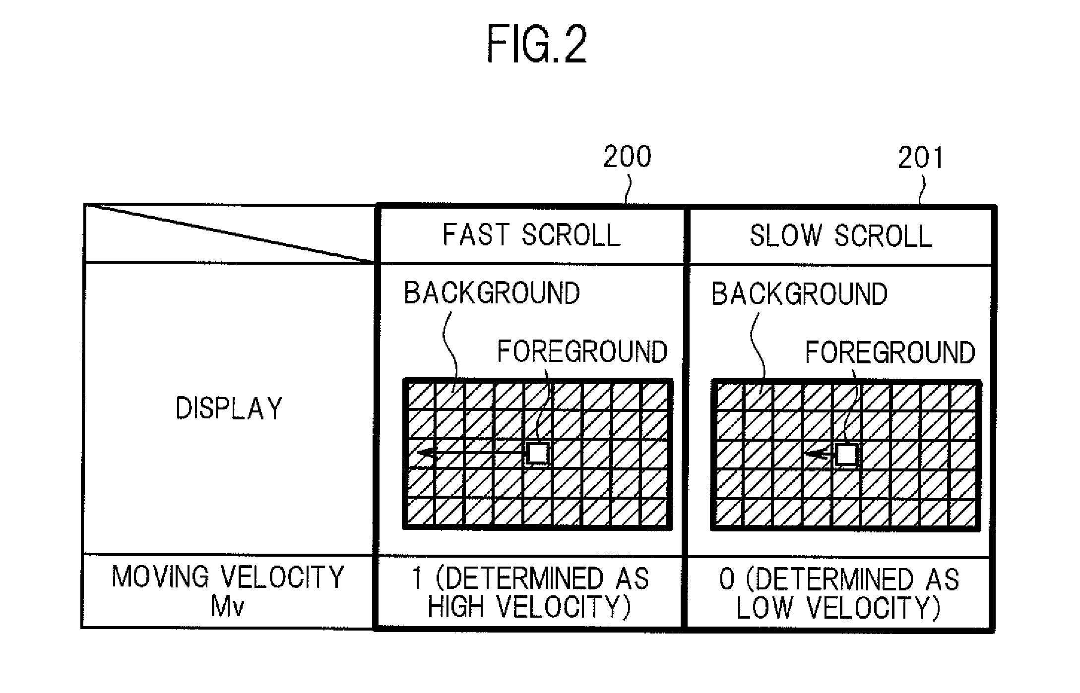
[0031]In the display device according to the first embodiment, it is detected whether a display in which an object in a video corresponding to an input video moves at higher velocity (for example, a display in which the foreground moves at higher velocity) is provided or a display in which the object moves at lower velocity (for example, a display in which the foreground moves at lower velocity) is provided, and the luminance variations in one frame of the LED devices forming a backlight is automatically controlled for each LED device according to the detection result.

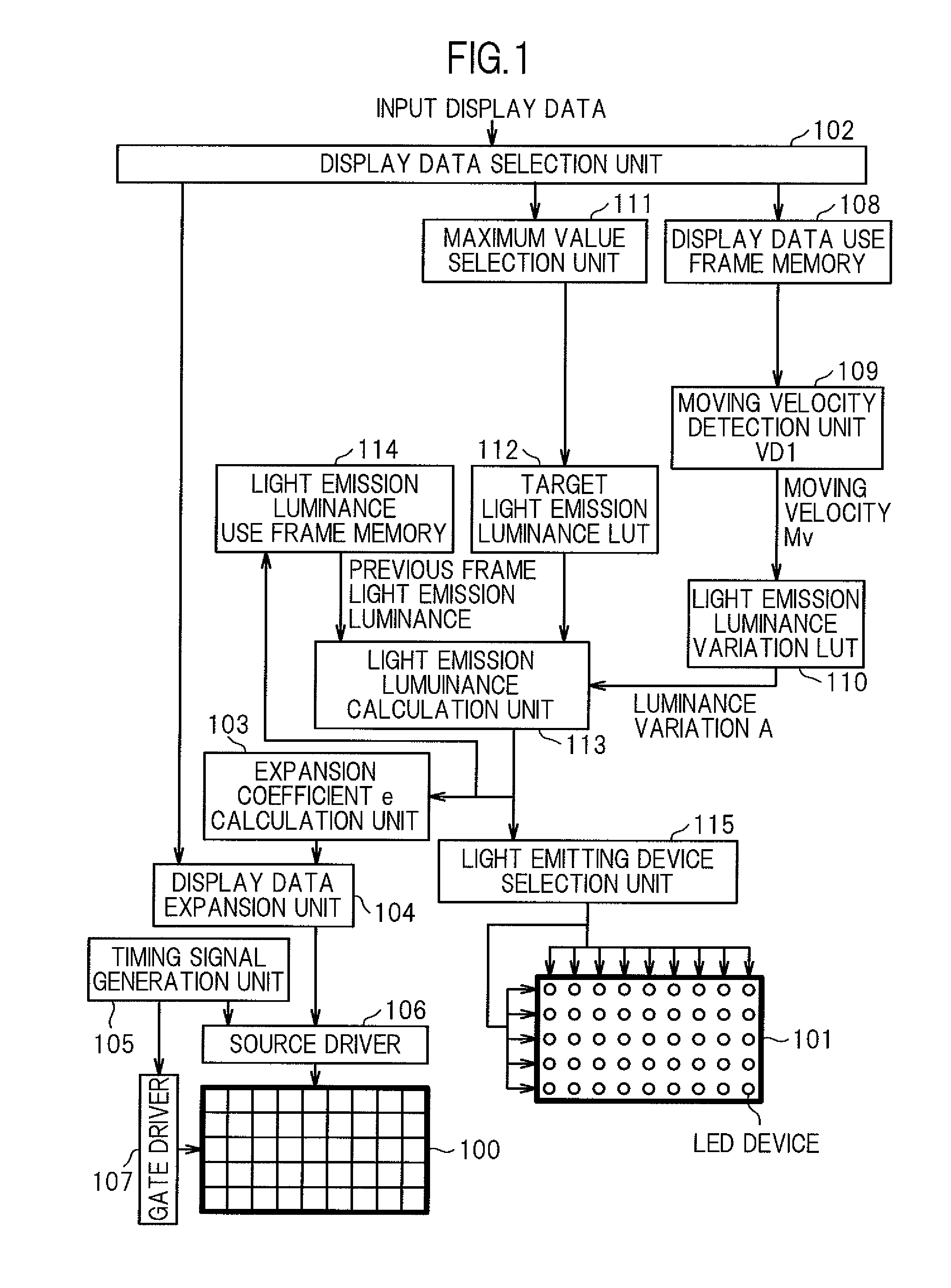
[0032]FIG. 1 is a diagram illustrating an example of the liquid crystal display device according to the first embodiment.

[0033]A display panel 100 includes, for example, a liquid crystal display panel in which display elements are arranged as pixels (display units) in a matrix of S columns and T rows (S and T...

second embodiment

[Second Embodiment]

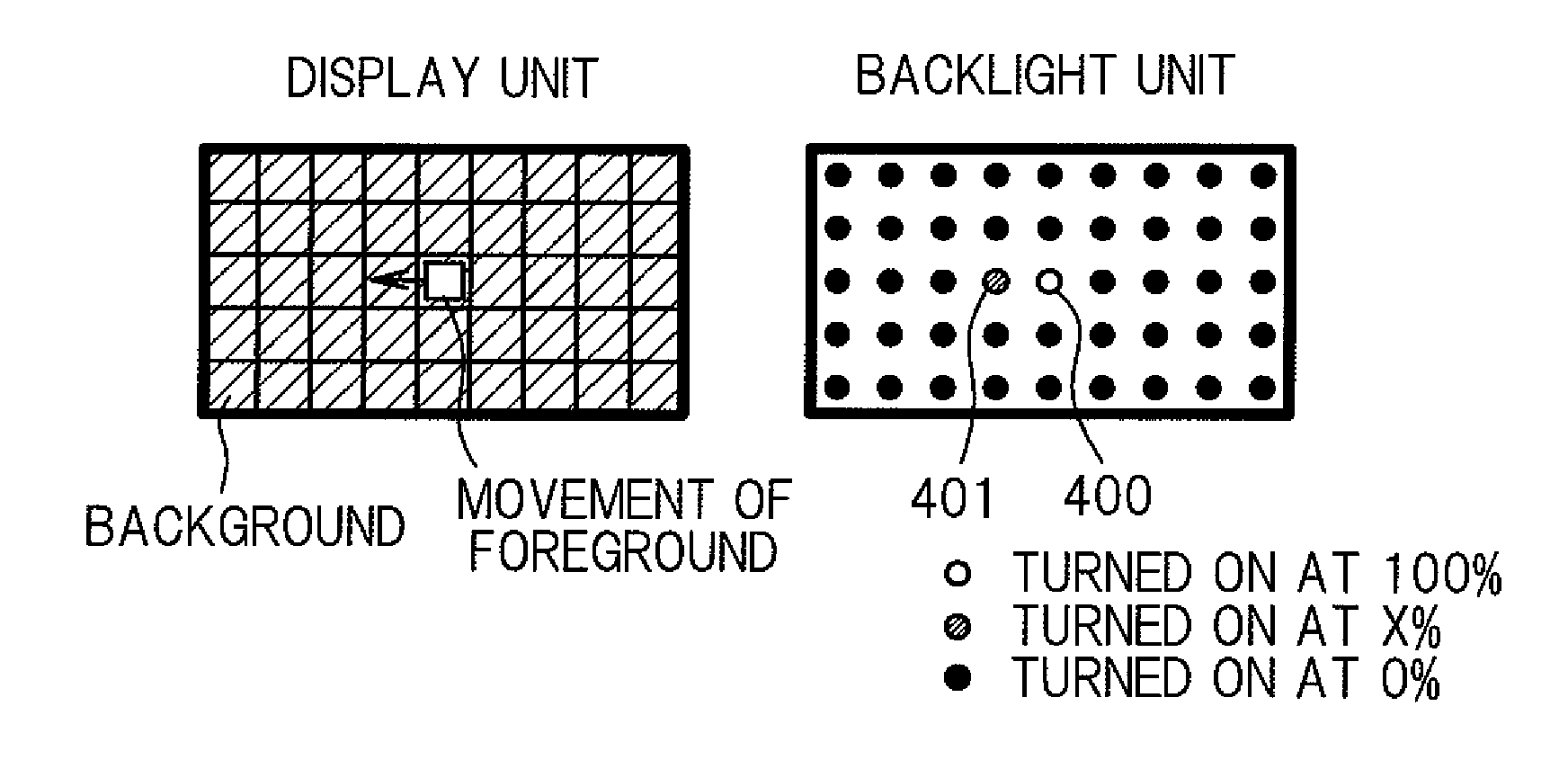
[0063]A second embodiment of the present invention is described with reference to FIGS. 4 and 5. In the first embodiment, when a displayed object in a video moves at lower velocity, the luminance variation of the LED backlight is controlled to be small, which has a negative side that it takes time for the LED backlight to reach a target luminance, with the result that the display luminance reduces until the target luminance is reached. In order to work around the problem, in a display device according to the second embodiment, a move destination of a display object is estimated, and the LED luminance in the area of the move destination is increased in advance to around the target value. In other words, as compared with the display device according to the first embodiment in which only an LED 400 for irradiating a foreground is turned on as illustrated in FIG. 4A, in the display device according to the second embodiment, the luminance of an LED 401 in the moving di...

third embodiment

[Third Embodiment]

[0070]A third embodiment of the present invention is described with reference to FIGS. 6 to 9. The first embodiment requires the display data use frame memory 108 for determining the moving velocity of an object in an input video, which increases the cost. In view of the above, the third embodiment is capable of producing an effect similar to that of the first embodiment, without the need for the display data use frame memory 108 of the first embodiment.

[0071]An operating principle of the third embodiment is described with reference to FIGS. 6A and 6B. FIG. 6A is a diagram illustrating, by taking a display unit in which the foreground moves at higher velocity as an example, a display before and after the movement of the foreground, and a backlight unit in which the LED device corresponding to the foreground is turned on at 100% and LED devices surrounding the LED device are turned on at X %. X is defined as 0

[0072]FIG. 6B is a diagram illustrating, by taking...


PUM


Abstract

Provided is a display device capable of producing an image of excellent quality with reduced flicker and little reduction in luminance, the display device including: a backlight having light sources such as LED devices arranged two-dimensionally, each of which may be individually modulated in luminance; a moving velocity detection unit VD1 (109) for detecting a moving velocity of an object in a video (for example, moving velocity of a foreground); and a luminance variation control unit (113) for automatically controlling luminance variations of the LED devices for each frame, in accordance with the moving velocity.

Description

CROSS-REFERENCE TO RELATED APPLICATION[0001]The present application claims priority from Japanese application JP2009-101137 filed on Apr. 17, 2009, the content of which is hereby incorporated by reference into this application.BACKGROUND OF THE INVENTION[0002]1. Field of the Invention[0003]The present invention relates to a display device, and more particularly, to a display device suited to displaying a moving image.[0004]2. Description of the Related Art[0005]Heretofore, a backlight using a cold cathode fluorescent lamp (CCFL) has been mainly used for a backlight of a liquid crystal display device. However, in recent years, further research has been conducted on a backlight using a light emitting diode (LED) device. JP 2001-142409 A (hereinafter, referred to as Patent Document 1) discloses a representative example of such a backlight using an LED device.[0006]Patent Document 1 discloses the following method. At least one LED, which serves as a light source for emitting illuminatin...

Claims


Application Information

Patent Timeline
Patent Type & Authority Patents(United States)
IPC IPC(8): G09G3/36
CPCG09G3/3426G09G2320/0247G09G2320/0261G09G2320/062
Inventor TOSHIMA, GOKIMARUYAMA, JUNICHIHOSOGI, KOJIOWA, MISAONO, KIKUO
Owner PANASONIC LIQUID CRYSTAL DISPLAY CO LTD
Why Eureka
Try Eureka