Image forming apparatus and feed mechanism

a technology of image forming apparatus and feed mechanism, which is applied in the direction of thin material processing, article separation, transportation and packaging, etc., can solve the problems of user forgetfulness, malfunction, and the inability of feed roller detection to be used, so as to achieve the effect of suppressing malfunction

Inactive Publication Date: 2013-09-17
KYOCERA DOCUMENT SOLUTIONS INC
View PDF10 Cites 3 Cited by
  • Summary
  • Abstract
  • Description
  • Claims
  • Application Information

AI Technical Summary

Benefits of technology

[0012]The present invention has an object of providing an image forming apparatus having a feed mechanism that can suppress malfunctions that may arise in a state in which a separation unit including a separation member is not installed.
[0013]In addition, the present invention has an object of providing a feed mechanism that can suppress malfunctions that may arise in a state in which the separation unit is not installed.

Problems solved by technology

In this operation, a user may forget to install the new feed roller or pad unit into the feed mechanism when replacing the feed roller or pad unit.
In a case of the feed mechanism being operated in a state in which the user has forgotten to install the new feed roller or pad unit, a malfunction will occur such as a paper jam in the feed mechanism.
However, with such a feed mechanism, the feed roller detection means is not a means for detecting the presence of the pad unit including the separation pad member.
In addition, the pad unit including the separation pad member is covered by the feed roller in the state installed in the feed mechanism, and thus it may be difficult to determine whether it is installed or not from outside.
In such a case, there has been a problem in that a severe paper jam occurs from a plurality of sheets of paper being fed at one time when the feed roller is rotationally driven.
Moreover, there has been a problem in that a failure will occur in the feed mechanism or the image forming apparatus equipped with this feed mechanism due to such a severe paper jam.

Method used


Image

  • Image forming apparatus and feed mechanism
  • Image forming apparatus and feed mechanism
  • Image forming apparatus and feed mechanism

Examples


Embodiment Construction

[0030]Hereinafter, preferred modes for carrying out the present invention will be explained while referring to the drawings.

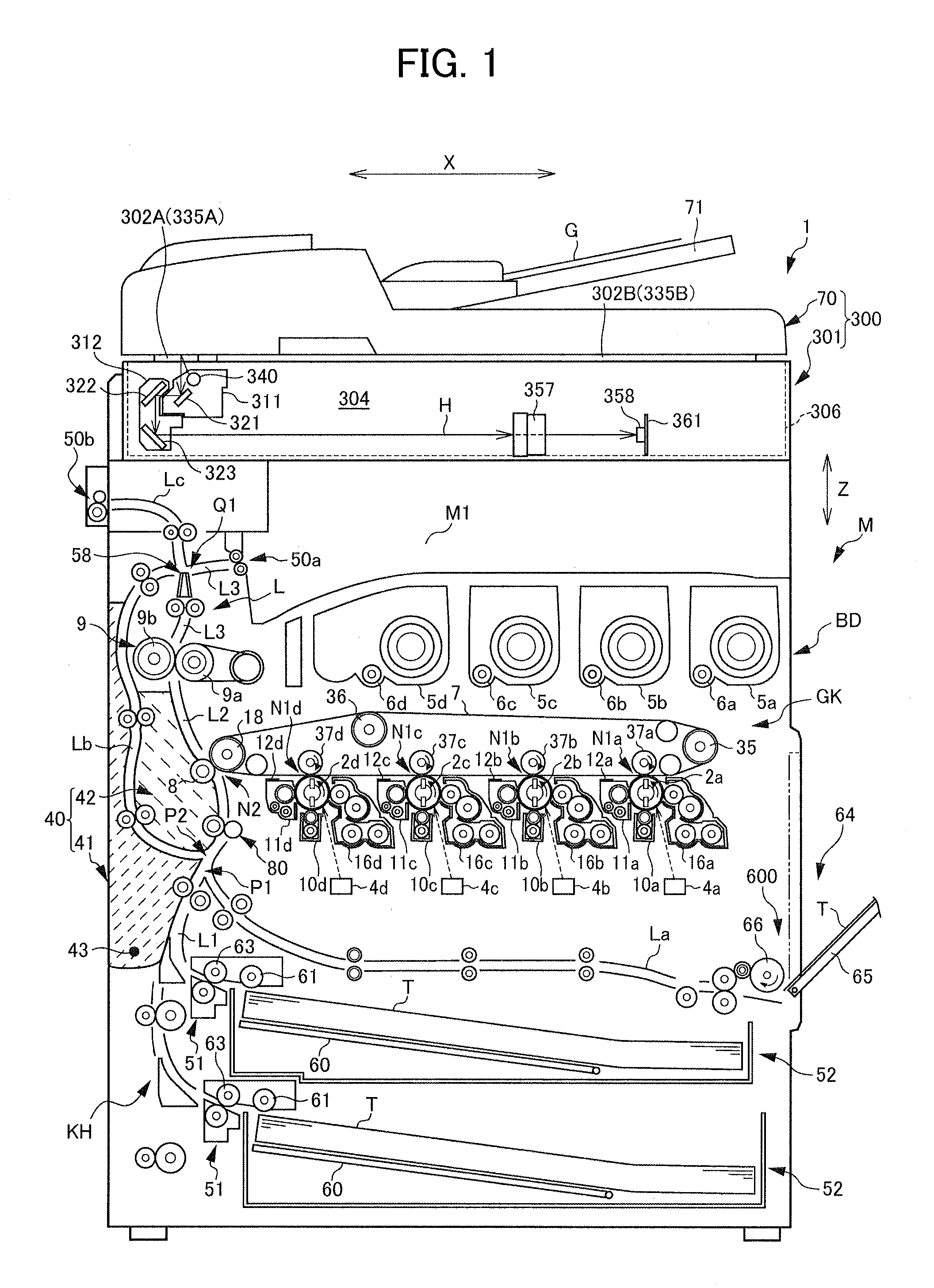
[0031]The overall configuration of a copy machine 1 as an image forming apparatus of the present embodiment will be explained according to FIG. 1. FIG. 1 is a view illustrating an arrangement of each constitutional element of the copy machine 1.

[0032]As shown in FIG. 1, the copy machine 1 as an image forming apparatus includes an image reading device 300 that is disposed at an upper side of the copy machine 1 in the vertical direction Z, and an apparatus main body M that is disposed at a lower side of the copy machine 1 in the vertical direction Z and forms a toner image on paper T, which serves as an image formation target material of sheet-shape, based on image information read from the image reading device 300.

[0033]It should be noted that, in the explanation of the copy machine 1, the sub scanning direction X is also referred to as the “horizontal direction...


PUM


Abstract

An image forming apparatus, comprising: a feed roller; a separation unit; a position detection part includes: a detection member that can move to a retracted position, and a detector which detects that a image formation target material is disposed at the feed position or the feed setup position in a case of having detected that the detection member is at the retracted position; and a restricting member that is disposed at a restricting position that restricts the detection member from moving from the initial position to the retracted position by abutting the detection member, in a detached state in which the separation unit is detached from the mounting part.

Description

[0001]This application is based on and claims the benefit of priority from Japanese Patent Application No. 2010-173844, filed on 2 Aug. 2010, the content of which is incorporated herein by reference.BACKGROUND OF THE INVENTION[0002]1. Field of the Invention[0003]The present invention relates to an image forming apparatus having a feed mechanism that feeds image formation target materials. In addition, the present invention relates to a feed mechanism that feeds image formation target materials.[0004]2. Related Art[0005]Conventionally, image forming apparatuses such as copy machines include a housing in which an image forming portion is disposed to be housed, and a feed mechanism (device) that feeds paper (image formation target materials) into the housing.[0006]The feed mechanism of an image forming apparatus typically includes a feed roller that feeds paper (image formation target material) to inside of the housing, and a pad unit (separation unit) that has a separation pad member ...

Claims


Application Information

Patent Timeline
Patent Type & Authority Patents(United States)
IPC IPC(8): B65H3/52
CPCB65H3/5223B65H2402/64B65H2405/324B65H2407/10B65H2407/21B65H2511/514B65H2553/612B65H2801/06B65H2701/1311B65H2220/01B65H2402/60B65H2553/61
Inventor YAMAMOTO, KIYONORI
Owner KYOCERA DOCUMENT SOLUTIONS INC
Why Eureka
Try Eureka