Centrifugal fan

a centrifugal fan and fan body technology, applied in the direction of machines/engines, stators, liquid fuel engines, etc., can solve the problem of limited airflow efficiency of centrifugal fans b>900/b>

Inactive Publication Date: 2013-09-17
CHAMP TECH OPTICAL FOSHAN
View PDF5 Cites 11 Cited by
  • Summary
  • Abstract
  • Description
  • Claims
  • Application Information

AI Technical Summary

Problems solved by technology

Thus the airflow efficiency of the centrifugal fan 900 is limited.

Method used


Image

  • Centrifugal fan
  • Centrifugal fan
  • Centrifugal fan

Examples


Embodiment Construction

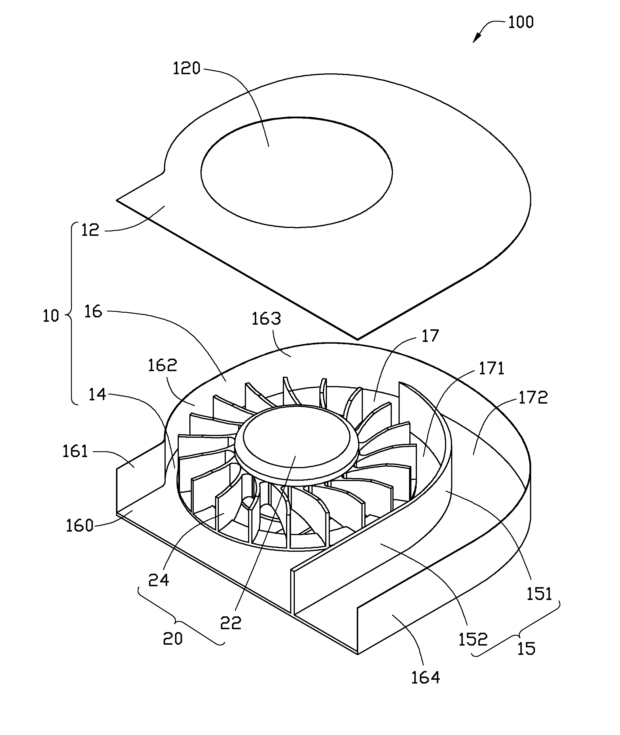
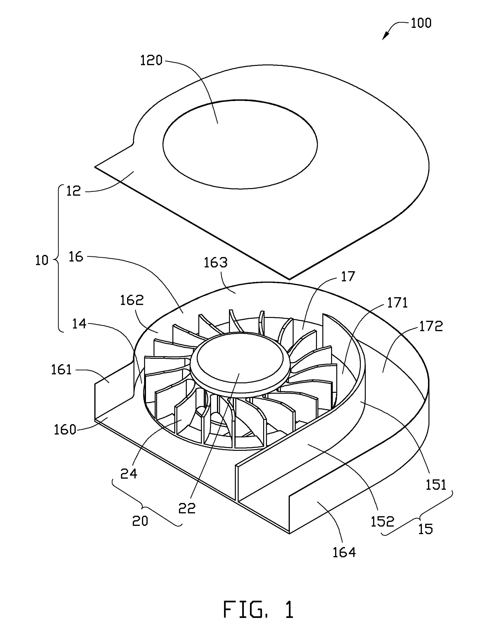
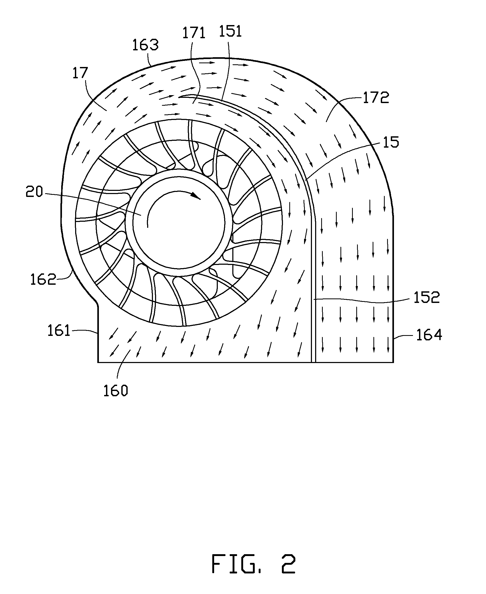
[0010]FIGS. 1 and 2 show a centrifugal fan 100 in accordance with an exemplary embodiment. The centrifugal fan 100 includes a casing 10, and an impeller 20 received in the casing 10. The impeller 20 includes a hub 22, and a plurality of blades 24 extending radially and outwardly from an outer periphery of the hub 22. The casing 10 includes a top cover 12, a bottom plate 14 corresponding to the top cover 12, and a volute sidewall 16 interconnecting circumferential portions of the top cover 12 and the bottom plate 14. The top cover 12, the bottom plate 14 and the sidewall 16 cooperatively define a receiving space (not labeled) therein. The impeller 20 is received in the receiving space.

[0011]The top cover 12 defines a through hole 120 in a central area thereof, the through hole 120 functioning as an air inlet 120. The impeller 20 is mounted to the bottom plate 14, and aligned with the air inlet 120 of the top cover 12. The sidewall 16 extends perpendicularly upwardly from a circumfere...


PUM


Abstract

An exemplary centrifugal fan includes a casing defining an air outlet, and an impeller in the casing. An air channel is defined in the casing between a sidewall of the casing and outermost free ends of the impeller. The sidewall includes a first curved section adjoining a second curved section. The first curved section is located at a more upstream portion of the sidewall than the second curved section along a rotation direction of the impeller. The first curved section extends along a part of an Archimedes spiral or a part of a logarithmic spiral. The second curved section is located farther away from the impeller than an imaginary extension line of the first curved section along the Archimedes spiral or the logarithmic spiral. An air guide plate is formed in the casing and extends from the air outlet to an inner region of the air channel.

Description

BACKGROUND[0001]1. Technical Field[0002]The present disclosure relates to centrifugal fans, and particularly to a centrifugal fan with strong airflow.[0003]2. Description of Related Art[0004]Thermal modules incorporated with a centrifugal fan are often applied to dissipate heat from heat generating components, such as central procession units (CPUs) in computers. The centrifugal fan is used to provide airflow to evacuate heat from the thermal module. FIG. 4 shows a commonly used centrifugal fan 900, which includes a casing 92 and an impeller 94 received in the casing 92. The casing 92 includes a volute sidewall 922 with an air outlet 920 defined at one side thereof. As shown in the coordinate system, four regions I, II, III, IV are formed respectively at four corners of the casing 92, and the sidewall 922 includes a curved section extending from a position in the region II anticlockwise through to the 0° axis. The casing 92 defines a corner portion 924 at the region III. During oper...

Claims


Application Information

Patent Timeline
Patent Type & Authority Patents(United States)
IPC IPC(8): F04D29/42F04D29/40F03D1/04
CPCF04D25/0613F04D29/4246
Inventor LIANG, EN-MINGYU, FANG-XIANGKUO, JER-HAUR
Owner CHAMP TECH OPTICAL FOSHAN
Why Eureka
Try Eureka