
Image pickup apparatus capable of releasing heat efficiently

a pickup apparatus and efficient technology, applied in the field of image pickup apparatus, can solve the problems of increasing the amount of heat released from the ic, increasing the power consumption, and local temperature of the grip portion, so as to achieve efficient heat release and prevent a local temperature rise in the grip portion

Active Publication Date: 2013-09-17
CANON KK
View PDF11 Cites 5 Cited by
  • Summary
  • Abstract
  • Description
  • Claims
  • Application Information

AI Technical Summary

Benefits of technology

The invention is about a mechanism that helps release heat generated by an image pickup element close to the outside of a grip that is being held by a user. This prevents the grip from getting too hot and makes the device comfortable to use.

Problems solved by technology

In an image pickup apparatus, such as a digital camera, throughput of an image pickup element and various ICs (integrated circuits) including driver ICs has increased with improvement in the capabilities of the image pickup apparatus, and accordingly power consumption has increased.
For this reason, there is a fear that an increase in the amount of heat released from an IC will locally increase the temperature of a portion of an exterior of the electronic apparatus close to the IC.
In the image pickup apparatus of this type, the image pickup element as a heat emitting element is disposed close to the exterior of a grip portion to be gripped by hand by a user, and hence the temperature of the grip portion is locally increased, which can feel odd or uncomfortable to the user.
However, the techniques disclosed in Japanese Patent Laid-Open Publication No. 2004-48517 and No. 2004-54159 cannot be employed for a heat releasing structure of this type of image pickup apparatus.

Method used


Image

  • Image pickup apparatus capable of releasing heat efficiently
  • Image pickup apparatus capable of releasing heat efficiently
  • Image pickup apparatus capable of releasing heat efficiently

Examples


Embodiment Construction

[0024]The present invention will now be described in detail below with reference to the accompanying drawings showing embodiments thereof.

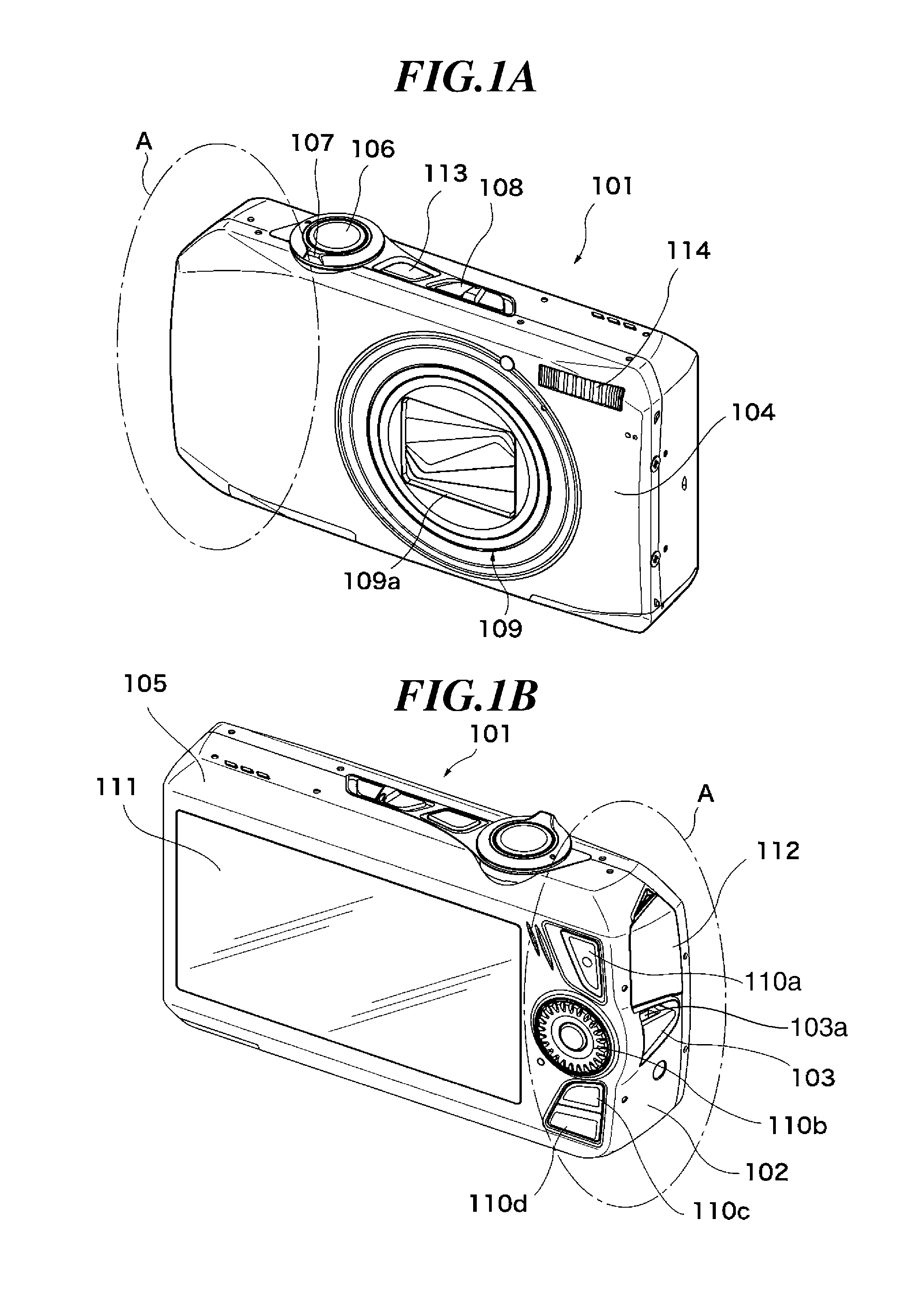
[0025]FIGS. 1A and 1B are perspective views of the appearance of a digital camera as an image pickup apparatus according to an embodiment of the present invention. FIG. 1A shows the digital camera as viewed from the front, and FIG. 1B shows the digital camera as viewed from the rear.

[0026]As shown in FIGS. 1A and 1B, the digital camera 101 of the present embodiment has an exterior thereof formed by a front cover 104, a rear cover 105, side covers 102 and 103, a terminal cover 112 for covering a terminal for communication with an external apparatus, and so forth. The side cover 103 is formed with a strap attachment part 103a.

[0027]On the front of the digital camera 101, there are arranged a zoom operation section 109a of a lens barrel 109 and a strobe light emission window 114. On the rear of the digital camera 101, there are arranged a display se...


PUM


Abstract

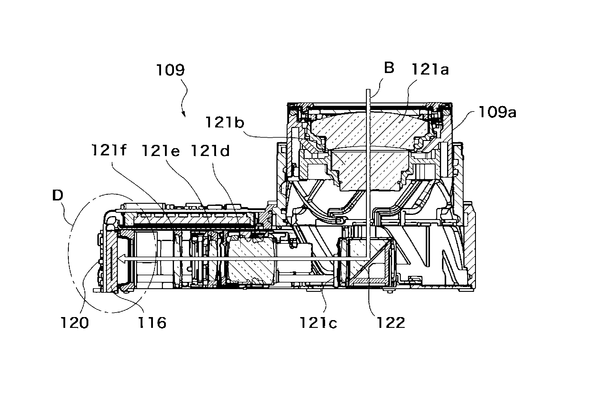
An image pickup apparatus capable of efficiently releasing heat generated by an image pickup element disposed close to an exterior of a grip portion, and thereby prevent a local temperature rise in the grip portion. A lens barrel bends a light flux incident from an object by a prism to guide the light flux toward the grip portion. The lens barrel is fixed to a chassis member. A front cover covers a portion of the lens barrel and is disposed such that the lens barrel is positioned between the chassis member and the front cover. An image pickup element is disposed toward the grip side. A heat conductive member is coupled to the chassis member and the front cover. Side covers cover the heat conductive member. The thermal conductivity of the side covers is smaller than that of the front cover.

Description

BACKGROUND OF THE INVENTION[0001]1. Field of the Invention[0002]The present invention relates to an image pickup apparatus, such as a digital camera, which is equipped with an image pickup element for photoelectrically converting an object image to an electric signal.[0003]2. Description of the Related Art[0004]In an image pickup apparatus, such as a digital camera, throughput of an image pickup element and various ICs (integrated circuits) including driver ICs has increased with improvement in the capabilities of the image pickup apparatus, and accordingly power consumption has increased. For this reason, there is a fear that an increase in the amount of heat released from an IC will locally increase the temperature of a portion of an exterior of the electronic apparatus close to the IC.[0005]Conventionally, as a technique of efficiently releasing heat generated within an image pickup apparatus, there has been proposed a digital camera provided with a heat release member having a h...

Claims


Application Information

Patent Timeline
Patent Type & Authority Patents(United States)
IPC IPC(8): H04N5/225
CPCG03B17/17G03B17/55H04N5/2253H04N5/2252G03B2217/002H04N23/51H04N23/54H04N23/50G03B17/02G03B17/56H04N23/52
Inventor ODAGAKI, KOICHI
Owner CANON KK
Learn More