Downhole sonic logging tool including irregularly spaced receivers

a receiver and sonic technology, applied in the field of subterranean formation acoustic logging, can solve the problems of aliasing of compressional arrival, affecting the arrival of shear wave, and affecting the accuracy of sonic logging, so as to reduce interference, reduce aliasing, and reduce the effect of aliasing

Inactive Publication Date: 2013-09-24
SCHLUMBERGER TECH CORP
View PDF38 Cites 7 Cited by
  • Summary
  • Abstract
  • Description
  • Claims
  • Application Information

AI Technical Summary

Benefits of technology

[0009]Exemplary embodiments of the present invention provide several technical advantages. For example, the non-uniform spacing of the array of receivers advantageously reduces (or even substantially eliminates) aliasing when the received waveforms are processed, for example, to obtain semblance data. Reducing the aliasing effect advantageously reduces interference with shear wave arrivals. This is particularly advantageous in applications in which the received waveforms are processed downhole to obtain the semblance data and in which the downhole processor is further utilized to obtain (or pick) the shear wave slownesses from the semblance data.
[0010]Moreover, the use of non-uniformly spaced receivers in the present invention tends to enable the reduction in aliasing to be achieved with little or no loss of array coverage and little or no increase in the uncertainty in the coherence slowness analysis. These advantages can be further achieved without incurring additional fabrication costs (in that the acoustic measuring tool requires no additional receivers)

Problems solved by technology

Additionally, as used in the art, there is not always a clear distinction between the terms LWD and MWD.
One well known problem with this technique is that aliasing of the compressional arrival often interferes with a shear wave arrival.
This aliasing effect may mask or mimic the presence of a shear wave signal and tends to be particularly harmful when the alias is close to an expected shear wave arrival time.
However, reducing the receiver spacing also reduces array coverage unless more receivers are added.
Moreover, a reduction in receiver array coverage, which increases the uncertainty in the coherence slowness analysis.
Additional receivers to mitigate the reduction in array coverage are known to increase the cost and complexity of the downhole tool.

Method used


Image

  • Downhole sonic logging tool including irregularly spaced receivers
  • Downhole sonic logging tool including irregularly spaced receivers
  • Downhole sonic logging tool including irregularly spaced receivers

Examples


embodiment 100

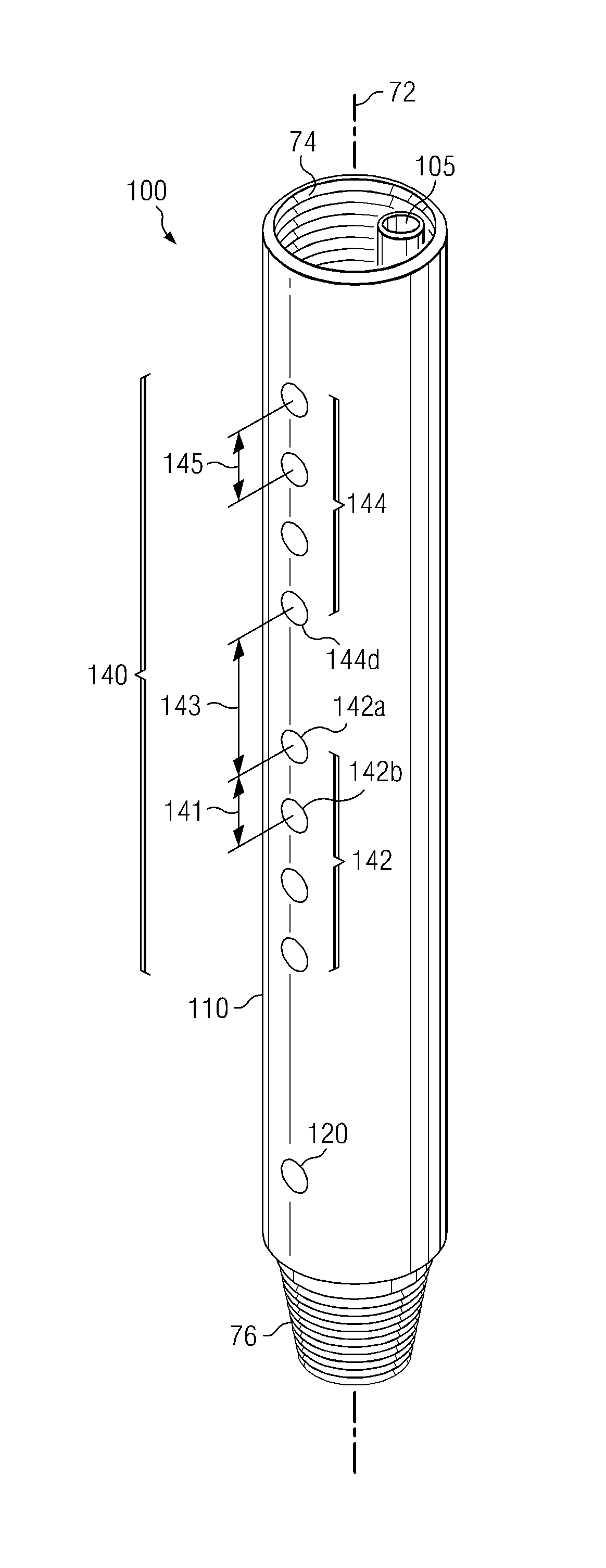
[0058]It is to be understood that the reduction of the aliasing effect of the present invention can be accomplished with other types of non-uniform receiver arrays. FIGS. 5 and 6 depict other embodiments having non-uniform receiver arrays. Tool embodiment 100′ depicted on FIG. 5 has a logging while drilling tool body 110 in which a transmitter 120 is longitudinally spaced apart from a non-uniformly spaced apart array 150 of acoustic receivers. Array 150 is arranged so that a first subarray 152 of receivers 152a-152d is interleaved with a second subarray 154 of receivers 154a-154d. In these embodiments an interarray distance 153 can be defined as the minimum spacing between an acoustic receiver of the first subarray and an acoustic receiver of the second subarray, for example, the distance between receiver 152b of the first subarray and receiver 154a of the second subarray. The invention is not limited to embodiments in which the subarrays 152 and 154 are fully interleaved. In other ...


PUM


Abstract

A downhole acoustic measurement tool includes at least one transmitter longitudinally spaced apart from a non-uniformly spaced longitudinal array of acoustic receivers. The array has a non-uniform spacing such that a first spacing between a first pair of consecutive acoustic receivers in the array is not equal to a second spacing between a second pair of consecutive acoustic receivers in the array. Non-uniform spacing of the receivers in the array reduces aliasing when the received waveforms are processed, for example, to obtain semblance data.

Description

RELATED APPLICATIONS[0001]None.FIELD OF THE INVENTION[0002]The present invention relates generally to acoustic logging of subterranean formations. More particularly, this invention relates to an acoustic measurement tool configured to reduce aliasing effects.BACKGROUND OF THE INVENTION[0003]The use of acoustic (e.g., audible and / or ultrasonic) measurement systems in prior art downhole applications, such as logging while drilling (LWD), measurement while drilling (MWD), and wireline logging applications, is well known. Such acoustic measurement systems are utilized in a variety of downhole applications including, for example, borehole caliper measurements, measurement of drilling fluid properties, and the determination of various physical properties of a formation. In one application, acoustic waveforms may be generated at one or more transmitters deployed in the borehole. The acoustic responses may then be received at an array of longitudinally spaced apart receivers deployed in the...

Claims


Application Information

Patent Timeline
Patent Type & Authority Patents(United States)
IPC IPC(8): G01V1/00
CPCG01V1/46
Inventor WANG, TSILI
Owner SCHLUMBERGER TECH CORP
Why Eureka
Try Eureka