Multi-spot transmission and reception system on board a satellite and satellite comprising such a system

a multi-spot transmission and reception system technology, applied in radio transmission, frequency-division multiplex, electrical equipment, etc., can solve the problems of not allowing the implementation of direct inter-spot links between users, limitations that do not permit the processing of a large number of connections between, and reducing the number of conversion channels upstream, reducing size and mass, and reducing complexity

Active Publication Date: 2013-09-24
THALES SA
View PDF11 Cites 1 Cited by
  • Summary
  • Abstract
  • Description
  • Claims
  • Application Information

AI Technical Summary

Benefits of technology

[0009]A first object of the invention is to implement a new repeater architecture on board a satellite which does not include the disadvantages of the existing architectures, enabling the implementation of uplinks and downlinks between one or more earth stations and user spots and enabling the implementation of a large number of direct inter-spot links between the users and using a DTP of reduced size and mass, with minimised complexity, having a number of input and output access points which is much lower than the number of user inter-spot connections to be implemented and enabling minimisation of the number of conversion channels upstream and downstream of the DTP.
[0010]A second object of the invention is to implement a new repeater architecture allowing a set of user spots to be served even if the number of stations on the ground is insufficient.

Problems solved by technology

Current architectures do not allow the implementation of direct links between the users, referred to as inter-spot links or mesh links, and impose a fixed connectivity between the spots of the users and the earth stations.
This type of architecture only allows the provision of uplinks and downlinks between earth stations and user spots and does not allow the implementation of direct inter-spot links between users.
These limitations do not permit the processing of a large number of connections between the spots 36 to be retransmitted and the destination spots 43.
For example, in the case of 80 user spots, 160 frequency conversion channels are necessary, which increases the complexity of the architecture around the DTP 31, the number of conversion channels on either side of the DTP and the DTP itself.

Method used


Image

  • Multi-spot transmission and reception system on board a satellite and satellite comprising such a system
  • Multi-spot transmission and reception system on board a satellite and satellite comprising such a system
  • Multi-spot transmission and reception system on board a satellite and satellite comprising such a system

Examples


Embodiment Construction

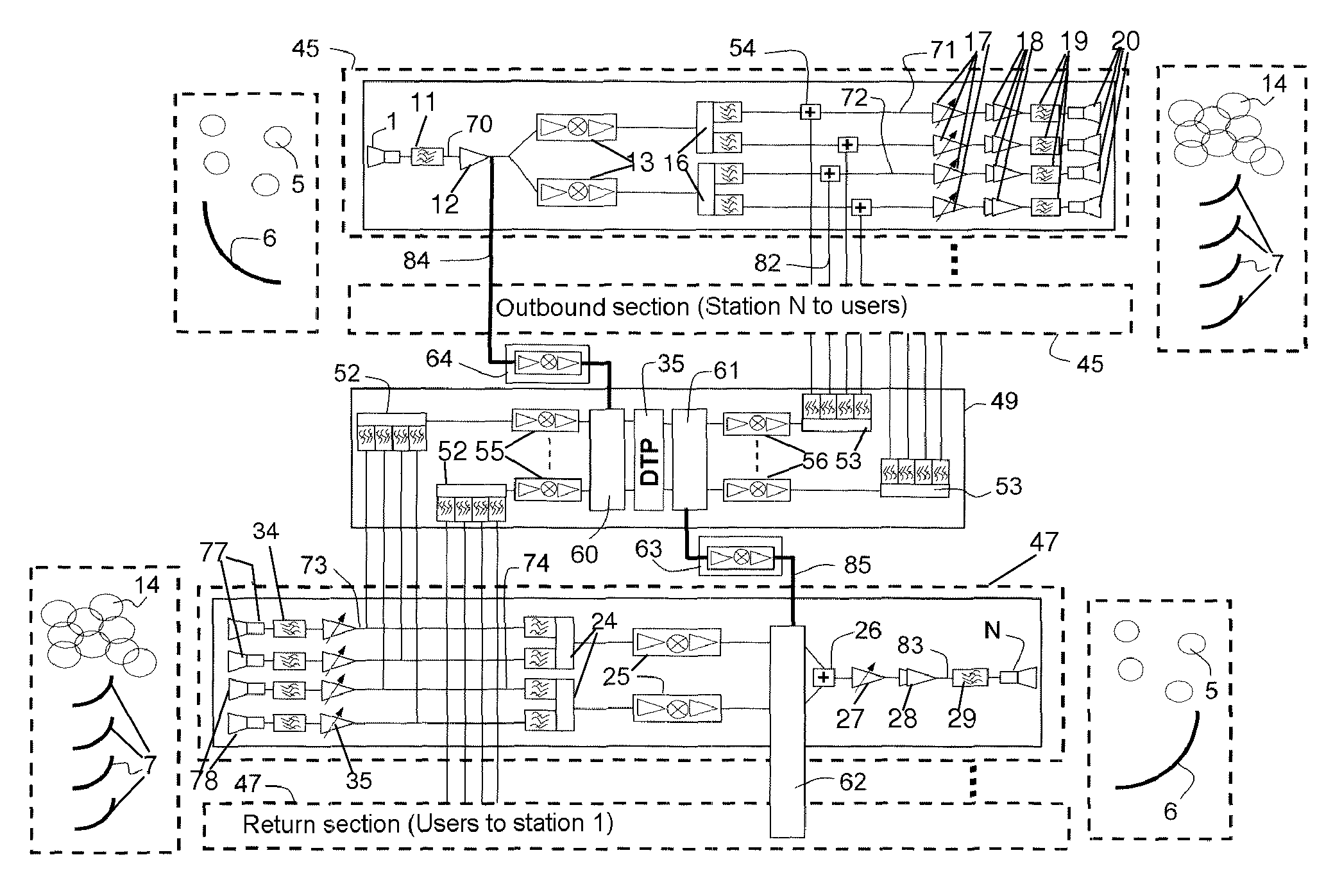
[0034]The payload architecture shown in FIG. 4 comprises at least one outbound section 45 comprising a hub reception channel 70 to receive signals 5 originating from an earth station (not shown) and to provide the routing of these signals 5 to user spots 14 via at least two user transmission channels 71, 72, at least one return section 47 comprising at least two user reception channels 73, 74 to receive signals originating from user spots 14, and to provide the routing of the received signals to an earth station via a hub transmission channel 83, and a mesh section 49 providing direct inter-spot links between the users. The number of outbound sections is equal to the number of return sections.

[0035]The transmission of the communications between one or more earth stations and a plurality of user spots 14 is implemented via transmission and reception antennas 7 dedicated to user spots 14 and at least one hub transmission and reception antenna 6 comprising hub transmission and receptio...


PUM


Abstract

A multi-spot transmission and reception system includes at least one outbound section implementing the reception of a hub frequency band and its transposition into user transmission sub-bands, at least one return section implementing the reception of user frequency sub-bands, and their transposition into a hub transmission band and a mesh section comprising a digital transparent processor DTP. The mesh section includes: frequency sampling and recombining means to sample, on user reception sub-bands a mesh band fraction, and to recombine the sampled mesh band fractions on an input of the DTP; and frequency division and reinjection means to divide the frequency band routed to an output of the DTP, into band fractions, and to reinject the band fractions obtained into the user transmission sub-bands. An application of the system is to repeaters on board telecommunications satellites.

Description

CROSS-REFERENCE TO RELATED APPLICATION[0001]This application claims priority to foreign French patent application No. FR 0906178, filed on Dec. 18, 2009, the disclosure of which is incorporated by reference in its entirety.FIELD OF THE INVENTION[0002]The present invention relates to a multi-spot transmission and reception system on board a satellite and a satellite comprising such a system. It applies notably to the field of satellite telecommunications and, more particularly, to high definition television applications and multimedia applications.BACKGROUND OF THE INVENTION[0003]For high definition television applications and multimedia applications, the repeaters mounted on board known communication satellites comprise multi-spot transmission and reception systems which are based on transparent architectures offering uplinks between one or more earth stations and the repeater and downlinks between the repeater and a plurality of users. Current architectures do not allow the impleme...

Claims


Application Information

Patent Timeline
Patent Type & Authority Patents(United States)
IPC IPC(8): H04B7/185H04B7/204
CPCH04B7/18515H04B7/2041
Inventor VOISIN, PHILIPPELEBOULC'H, DIDIERTRANCART, BRUNO
Owner THALES SA
Why Eureka
Try Eureka