Conducting electric device for electric switch equipment

A conductive connection and electrical switch technology, which is applied in the direction of switchgear, switchgear setting, electrical components, etc., can solve the problems of large volume and mass of the contact seat, high manufacturing cost, etc. The effect of large volume and mass, reducing the difficulty of processing

Inactive Publication Date: 2012-10-03
HENAN PINGGAO ELECTRIC +1
View PDF4 Cites 0 Cited by
  • Summary
  • Abstract
  • Description
  • Claims
  • Application Information

AI Technical Summary

Problems solved by technology

[0003] The present invention proposes a conductive connection device for electrical switchgear, aiming at solving the p

Method used


Image

  • Conducting electric device for electric switch equipment
  • Conducting electric device for electric switch equipment

Examples


Example Embodiment

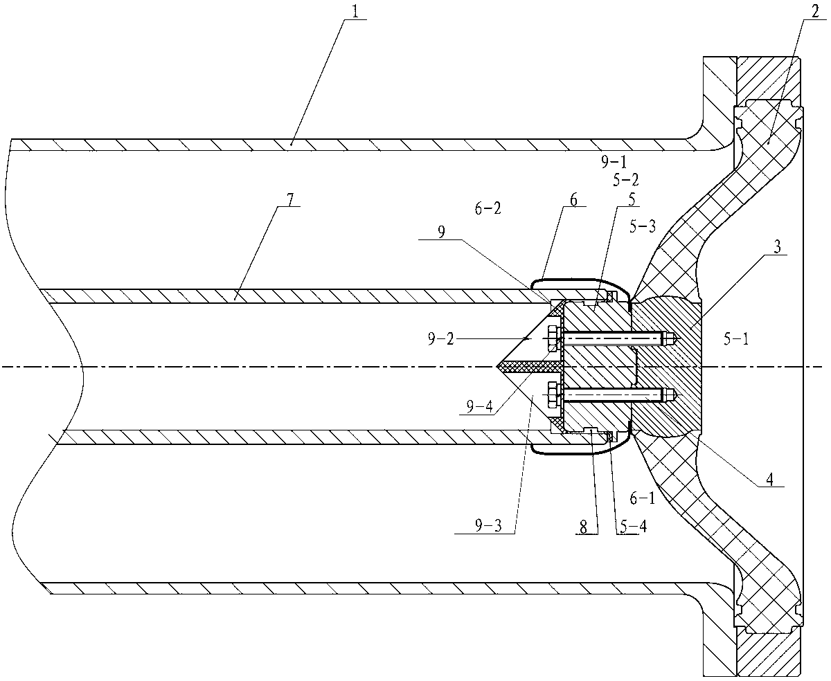
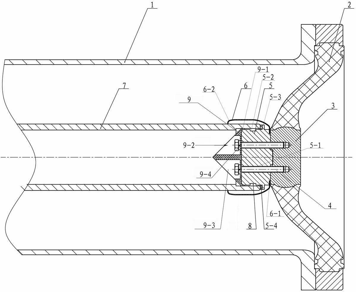
[0014] The embodiment of the conductive connection device for the electrical switchgear of the present invention: figure 1 As shown, the conductive connection device includes a cylindrical housing 1, an insulating basin 2 installed on the port of the housing 1, a connecting insert 3 of the insulating basin 2 and a cylindrical contact seat 5 that is detachably fixed by a connecting screw 4, A fixed shielding cover 6 is embedded between the contact base 5 and the connecting insert 3, a conductive tube 7 and a contact base inserted in the annular gap between the inner wall surface of the shielding cover 6 and the outer peripheral surface of the contact base 5 The spring contact fingers 8 installed on the outer circumference of the 5 and the insulating guide 9 that is detachably fixed at one end of the contact base 5 away from the connecting insert 3, wherein the conductive tube 7 and the bus conductor are integrally arranged so that the front end of the conductive tube 7 It has a ...


PUM


Abstract

The invention relates to a conducting electric device for electric switch equipment. The conducting connecting device is characterized in that two functions of electric field optimization and current carrying of a contact seat in the prior art are separated, the conducting connecting device is divided into a shielding cover used for electric field optimization and a contact seat used for being in charge of current carrying, a touch finger installing groove is positioned on the outer peripheral wall of the contact seat, and the outer peripheral surface of the guide end of an insulation guide element is exposed out from the outer peripheral surface of the contact seat to be in contact with the inner wall surface of a conducting tube, so the blind hole structure in the contact seat in the prior art is removed, the appearance size and the weight of the contact seat are reduced, in addition, the processing difficulty of the contact seat is lowered, the manufacture cost of the contact seat is reduced, and further, the problems of large own appearance size, heavy weight and high manufacture cost of the contact seat in the prior part are solved.

Description

technical field [0001] The invention relates to the technical field of electrical equipment, in particular to a conductive connection device for electrical switching equipment. Background technique [0002] At present, in gas-insulated metal-enclosed switchgear, there are mainly two types of contact between the bus bar and the electrical connection: crimping type and plug-in type. Among them, the plug-in type mostly uses contact seats with spring contacts or strap contacts, or in A spring contact finger or a watch strap contact finger is installed on the conductive tube. For example, the Chinese invention patent with application number 200820228958.6 discloses a conductive connection device for gas-insulated metal-enclosed switchgear. and the blind end of the blind hole is screwed to not only fix the contact seat on the connecting insert of the insulating basin, but also extend into the inner hole of the conductive tube to ensure the coaxiality of the conductive tube and th...

Claims


Application Information

Patent Timeline
IPC IPC(8): H02B13/035H01R13/46
Inventor 孙清超林麟贺晶晶雷传
Owner HENAN PINGGAO ELECTRIC
Why Eureka
Try Eureka