Unmanned autonomous vehicle for displacing feed

an autonomous vehicle and feed technology, applied in the direction of mechanical energy handling, multiple dynamo-electric motor speed regulation, analogue computers, etc., can solve the problem of little flexibility, and achieve the effect of more manageable or

Active Publication Date: 2013-09-24
LELY PATENT
View PDF46 Cites 1 Cited by
  • Summary
  • Abstract
  • Description
  • Claims
  • Application Information

AI Technical Summary

Benefits of technology

[0006]It is an object of the invention to provide an unmanned vehicle of the mentioned type which enables a more manageable or at least more flexible functioning.
[0007]According to the present invention, this object is achieved by means of an unmanned autonomous vehicle which comprises an adjusting device arranged to adjust the height and / or the position of a lowest point of a feed displacing device. This may comprise a vehicle tilting device which is arranged in such a manner that the lowest point will be located at least substantially outside the center line of the vehicle. By making the lowest point of the feed displacing device adjustable to be positioned not on the center line of the vehicle, the vehicle will be more flexibly controllable. In a vehicle with a rotatable feed displacing device whose lowest point, if defined, lies at the front on the center line of the vehicle, the feed displacing device provided for this vehicle will in principle be able to rotate in two directions, if the direction of rotation was not already set by an earlier encounter with feed or the like. The direction of rotation depends on the exact point on the feed displacing device where the resistance against the feed is encountered. However, by means of the vehicle according to the present invention, it is possible to adjust the feed displacing device, in particular the lowest point thereof, in such a manner that the first encounter with the feed, for example being encountered at slowly increasing feed height, will take place with greater certainty on the desired side of the center line of the vehicle.

Problems solved by technology

Moreover, it is pointed out that where previous vehicles comprise an angle adjustment, the lowest point continues to be located in principle at the same height and on the center line, so that there is little flexibility.

Method used


Image

  • Unmanned autonomous vehicle for displacing feed
  • Unmanned autonomous vehicle for displacing feed
  • Unmanned autonomous vehicle for displacing feed

Examples


Embodiment Construction

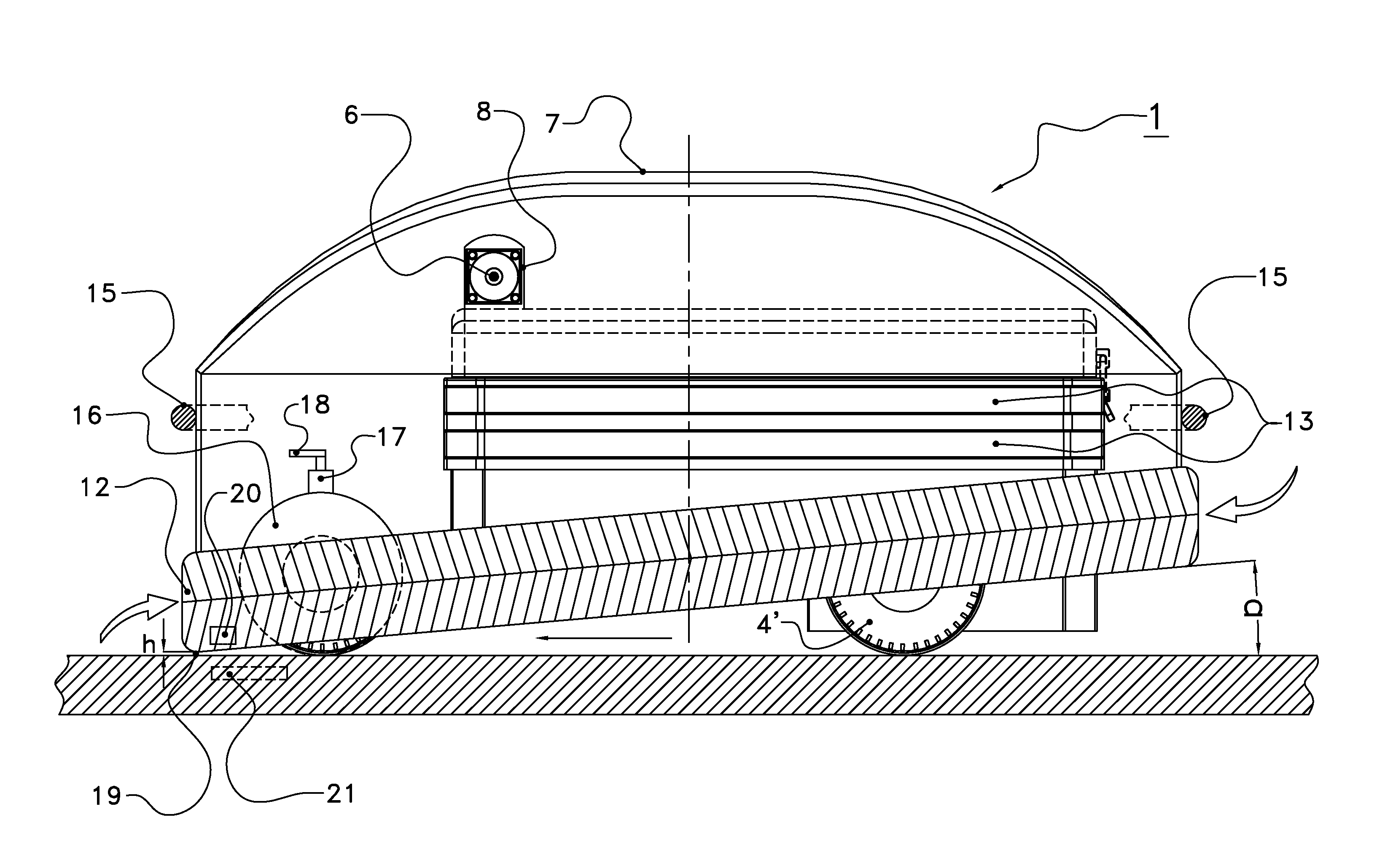
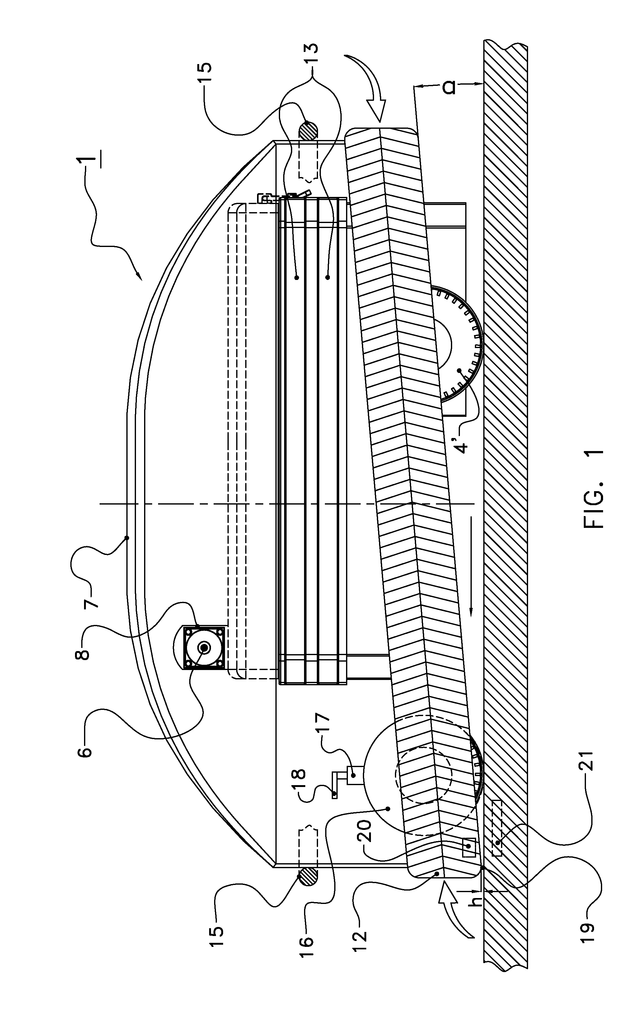
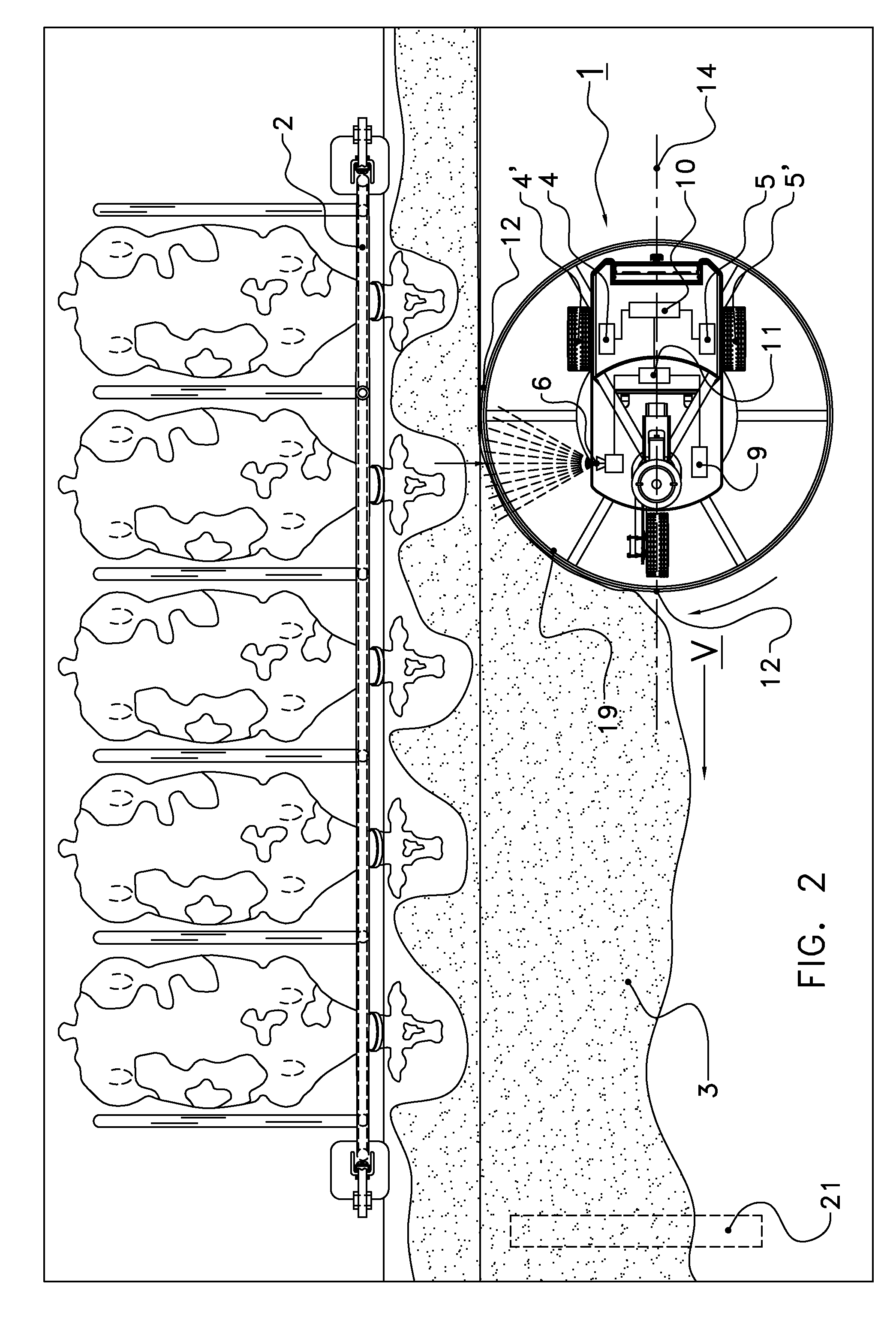
[0032]The following is a description of certain embodiments of the invention, given by way of example only and with reference to the drawings. FIGS. 1 and 2 show an unmanned autonomous vehicle 1 for substantially lateral displacement of feed 3 lying on the ground towards a feed fence 2. The feed 3, which may be solid, liquid or a mixture thereof, has been deposited at the feed fence 2 in a manner known per se, for example by means of a tractor. It will be obvious that the present invention is also applicable in other devices for supplying feed to animals, so that the feed fence shown in FIG. 2 is only one of the many examples of a wall portion in the vicinity of which feed can be deposited. In the present invention, by the term “wall portion” all forms of separating elements are meant, whether or not having an open structure, it being possible for the wall portion to assume many different, curved, rectilinear, angular, etc. shapes.

[0033]Autonomously displaceable vehicles, for perfor...


PUM


Abstract

An unmanned autonomous vehicle for substantially lateral displacement of feed lying on a ground, comprising two wheels separately drivable by separate drive units, a torque difference adjusting device for adjusting the torque difference between the wheels, a control unit for controlling the vehicle and moving it in a direction of travel by controlling at least one of the separate drive units, a feed displacing device for substantially lateral displacement of the feed, and an adjusting device which is arranged to adjust the height and / or the position of a lowest point of the feed displacing device. The adjusting device comprises a vehicle tilting device which is arranged in such a manner that the lowest point will be located at least substantially off the center line of the vehicle.

Description

[0001]This application is a continuation of international application no. PCT / NL2008 / 000248 filed on Nov. 10, 2008, which claims priority from Netherlands application no. 1034771 filed on Nov. 29, 2007, and this application is also a continuation-in-part of U.S. application Ser. No. 12 / 297,686 filed on Oct. 20, 2008, which is a continuation of international application no. PCT / NL2007 / 000083 filed on Mar. 23, 2007, which claims priority from Netherlands application no. 1031605 filed on Apr. 18, 2006. The contents of all of the foregoing applications are hereby incorporated by reference in their entirety.BACKGROUND OF THE INVENTION[0002]1. Field of the Invention[0003]The invention relates to an unmanned autonomous vehicle, and in particular to an unmanned autonomous vehicle comprising two wheels for substantially lateral displacement of feed lying on the ground.[0004]2. Description of the Related Art[0005]An unmanned autonomous vehicles for displacement of feed lying on the ground are...

Claims


Application Information

Patent Timeline
Patent Type & Authority Patents(United States)
IPC IPC(8): G06F17/00G06F19/00B60G17/016H02P5/46
CPCA01K1/105A01K5/0266
Inventor VAN DEN BERG, KAREL
Owner LELY PATENT
Why Eureka
Try Eureka