Low-power wireless device for asset-integrity monitoring

a low-power wireless and asset-integrity monitoring technology, applied in fluid-tightness measurement, instruments, processing detected response signals, etc., can solve the problems of reducing reducing the processing speed required, and reducing the peak power consumption of the sensor as a whole, so as to reduce the peak power consumption of the sensor, and reduce the overall capacitance of the sensor

Active Publication Date: 2019-11-05
SENSOR NETWORKS
View PDF10 Cites 0 Cited by
  • Summary
  • Abstract
  • Description
  • Claims
  • Application Information

AI Technical Summary

Benefits of technology

[0014]There are a number of important benefits flowing from a sensor using time-equivalent sampling, and the elimination of power-consuming components such as the A / D converter and FPGA. First, the elimination of these components lowers the peak power consumption of the sensor as a whole. Not only does this allow the use of smaller batteries, but also this configuration lowers the overall capacitance of the sensor as a whole. Lowering the capacitance is critical in making the sensor intrinsically safe for hazardous locations. Second, the elimination of components reduces the size of the device which renders it more manageable. Third, fewer components equate to lower cost. Still other benefits will be known to those of skill in the art in light of this disclosure.

Problems solved by technology

Although the integrated A / D converter is not as fast as a discrete A / D converter, and, thus may not facilitate the processing speeds required for real-time signal processing, Applicants have found that the slower A / D converter can perform time-equivalent sampling of multiple signal acquisitions to generate a composite signal with higher effective sampling rate.
First, the elimination of these components lowers the peak power consumption of the sensor as a whole.
Not only does this allow the use of smaller batteries, but also this configuration lowers the overall capacitance of the sensor as a whole.

Method used


Image

  • Low-power wireless device for asset-integrity monitoring
  • Low-power wireless device for asset-integrity monitoring
  • Low-power wireless device for asset-integrity monitoring

Examples


Embodiment Construction

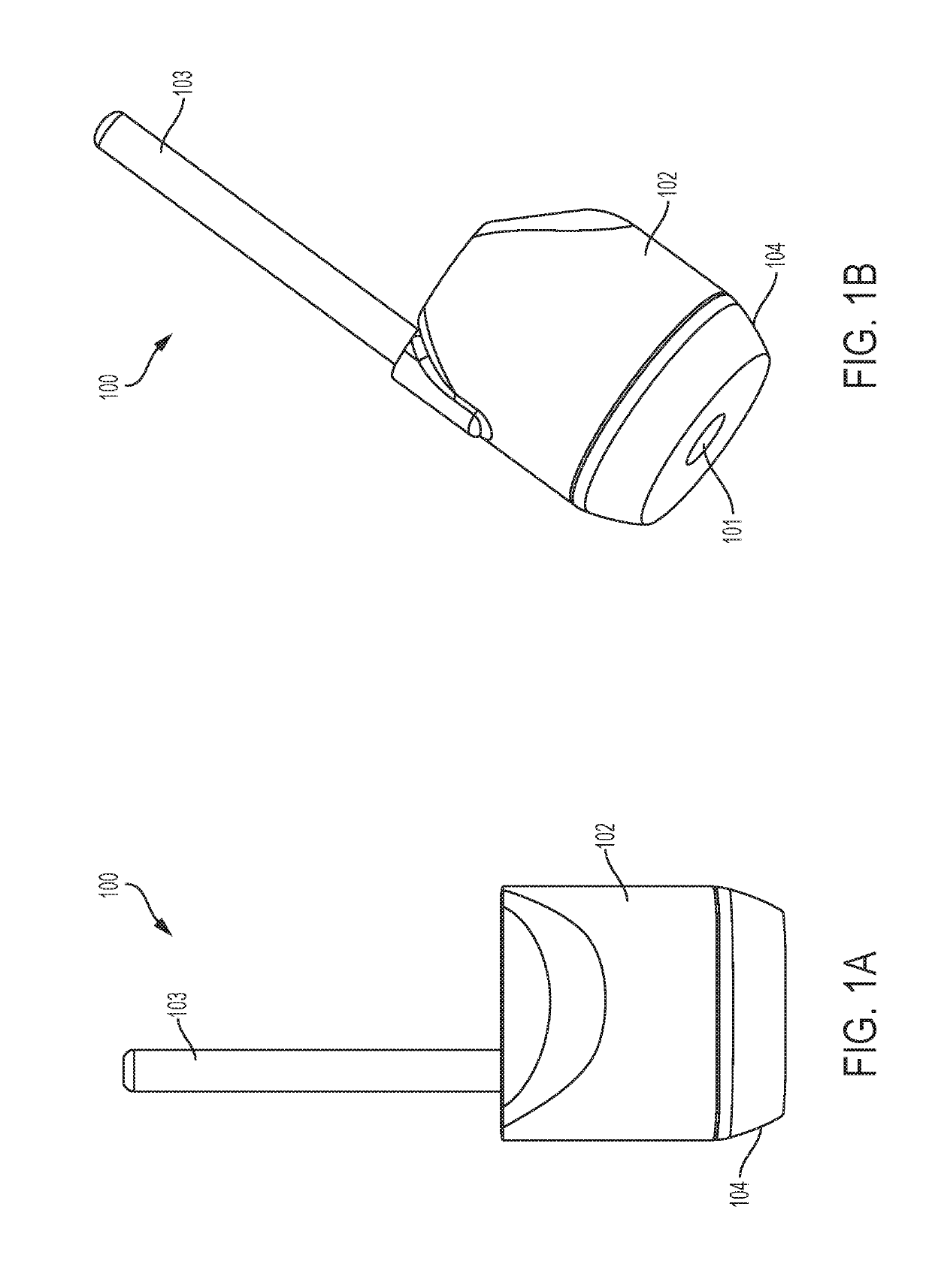
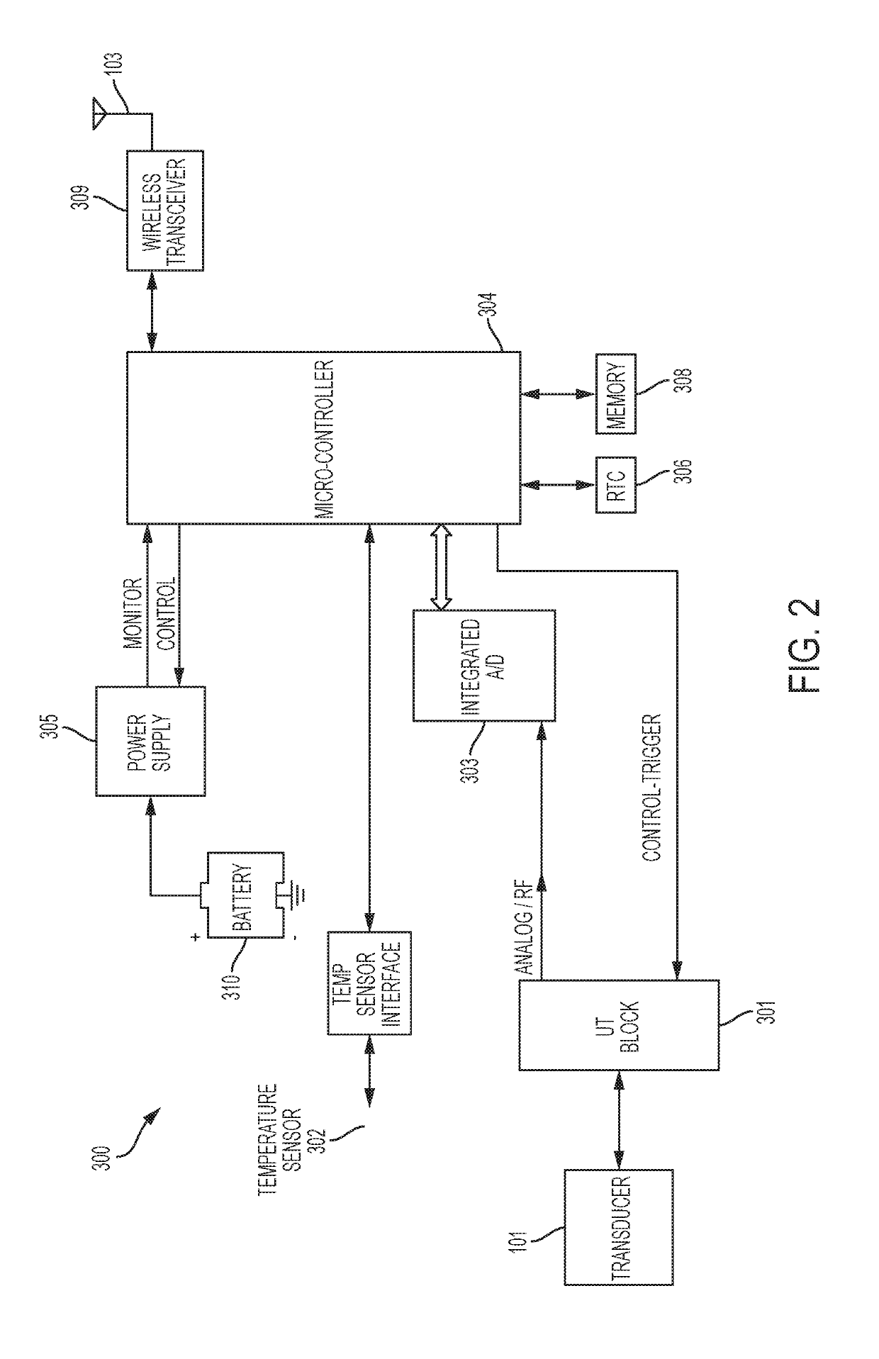
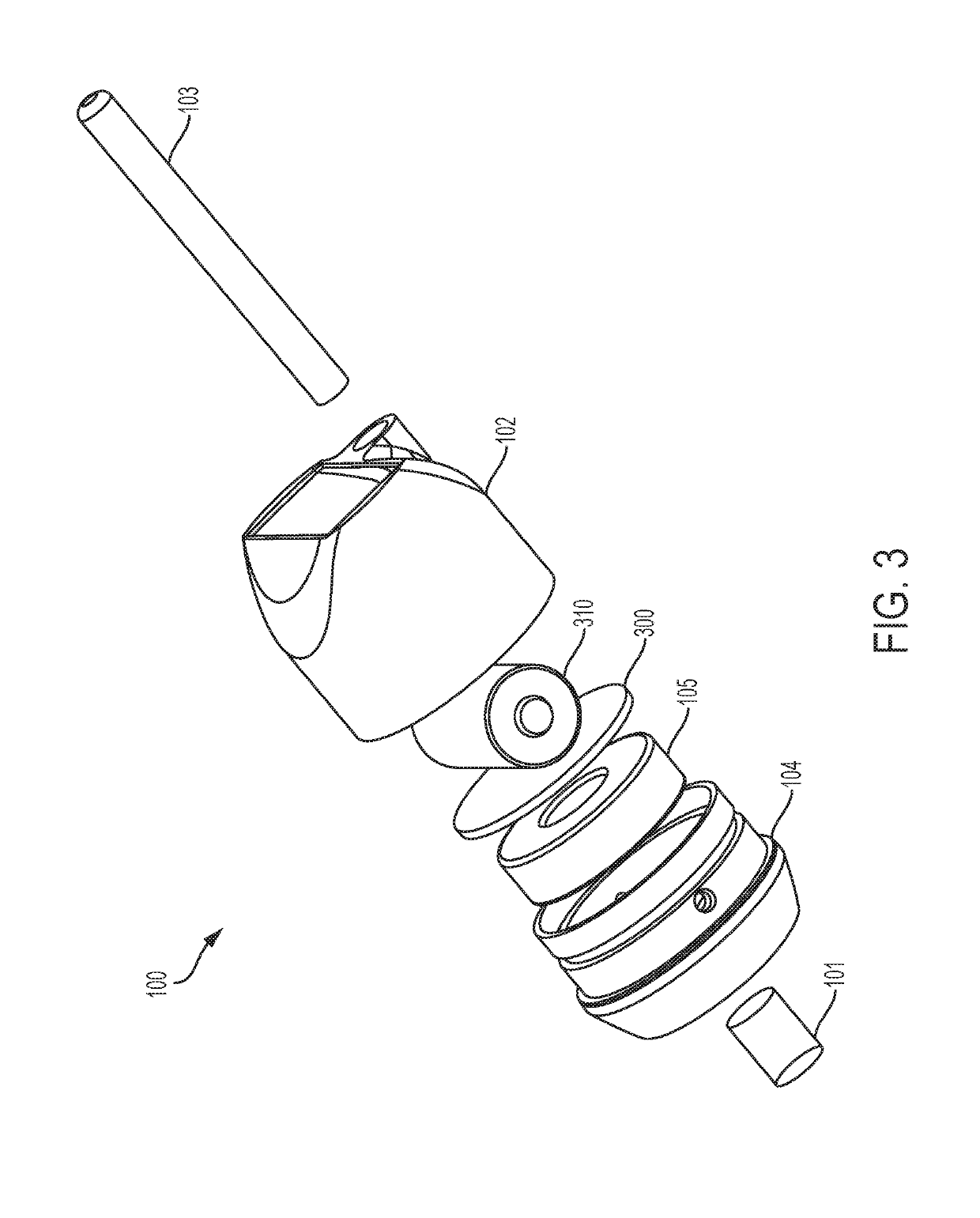
[0020]Referring to FIGS. 1A, 1B, 2, and 3, a perspective view and a schematic block diagram of one embodiment of the sensor 100 of the present invention is shown. The sensor is configured for measuring ultrasonically a portion of a structure. The sensor comprises a transducer 101 for converting an analog transmit signal to an ultrasonic transmit signal, and for converting an ultrasonic reflected signal to an analog reflected signal. The sensor also comprises a housing 102, which, in this embodiment, is integrated with the transducer to form a unitary package. The sensor also comprises at least the following contained in the housing: a processor 304; a wireless data transceiver 309 for transmitting wirelessly a data signal from the processor 304; a transmit and receive circuit 301 for transmitting an analog transmit signal to the transducer in response to a transmit trigger from the processor, and for receiving an analog reflected signal from the transducer; an A / D converter 303 for ...


PUM

PropertyMeasurementUnit
distancesaaaaaaaaaa
frequenciesaaaaaaaaaa
time-aaaaaaaaaa

Abstract

A sensor for ultrasonically measuring a portion of a structure, the sensor comprising: a transducer for converting an analog transmit signal to an ultrasonic transmit signal, and for converting an ultrasonic reflected signal to an analog reflected signal; a housing integrated with the transducer and containing at least: a processor; a wireless data transmitter for transmitting wirelessly a data signal from the processor; a transmit and receive circuit for transmitting an analog transmit signal to the transducer in response to a transmit trigger from the processor, and for receiving an analog reflected signal from the transducer; an A / D converter for digitizing only a portion of the analog reflected signal in response to a sample trigger from the processor; a battery to supply power to the processor, the wireless data transmitter, the transmit and receive circuit, and the A / D converter; memory operatively connected to the processor and configured to instruct the processor to execute the following steps: repeatedly triggering the transmit and receive circuit and the A / D converter to obtain a digitized composite signal through time-equivalent sampling; processing the digitized composite reflected signal to generate an A-scan signal; and wirelessly transmitting the data signal based on the A-scan signal for transmission to a discrete collection device.

Description

REFERENCE TO RELATED APPLICATION[0001]This application is based on U.S. Provisional Application No. 62 / 433,424 filed on Dec. 13, 2016, which is hereby incorporated by reference.FIELD OF INVENTION[0002]This invention relates to a device for ultrasonically monitoring the condition and integrity of pipes and / or other structures or assets, such as those used in the oil and gas and power generation industries using an improved, low-power and low-cost architecture.BACKGROUND[0003]Wall thickness and the presence of defects such as cracks are important factors in determining the fitness-for-service of structures such as above- and below-ground pipes and tanks, including bulk material and weldments. When a pipe is in operation, it can be subject to corrosion and / or erosion due to the content, flow and / or environmental conditions inside or outside of the pipe. Cracks can form and propagate due to the presence of manufacturing defects, creep, thermal cycling, fatigue and environmental conditio...

Claims


Application Information

Patent Timeline
Patent Type & Authority Patents(United States)
IPC IPC(8): H03M1/02G01N29/04G01N29/22G01N29/34G01N29/36G01N29/40G01N29/44G01N29/06G01N29/24G01N29/265H04B11/00G01M3/24G01B17/04G01N29/02
CPCG01N29/04G01N29/34G01N29/043H03M1/02G01M3/24G01N29/265G01N29/2481G01N29/36G01N29/0645G01N29/44G01N29/22G01M3/243G01N29/02G01N29/40G01B17/04H04B11/00G01N2291/044G01N2291/0258
Inventor FEYDO, MARKANDERSON, JEFFREYBARSHINGER, JAMES
Owner SENSOR NETWORKS
Why Eureka
Try Eureka