Pneumatic tire with tread having sipe

a technology of pneumatic tires and treads, applied in the field of pneumatic tires, can solve the problems of deterioration of braking performance or the like on ice road surfaces, and achieve the effects of reducing rigidity, well-balanced manner, and suppressing the displacement of the center of arrangemen

Active Publication Date: 2013-10-01
TOYO TIRE & RUBBER CO LTD
View PDF10 Cites 5 Cited by
  • Summary
  • Abstract
  • Description
  • Claims
  • Application Information

AI Technical Summary

Benefits of technology

[0009]The present invention is made by taking the actual condition mentioned above into consideration, and an object of the present invention is to provide a pneumatic tire which can secure an edge effect and a drainage effect by inhibiting an opening portion of a sipe from being narrowed as well as making a rigidity of a land portion proper in correspondence to a stage of progress of a wear and securing a collapse of the land portion.
[0015]In the pneumatic tire in accordance with the present invention, since the first sipe portion appears on the wheel tread in the process of the progress of the wear, and the second sipe portion and the third sipe portion appear subsequently, the sipe width becomes greater in accordance that the wear makes progress, and the land portion is lowered in its rigidity and tends to be deflected. As a result, it is possible to make the rigidity of the land portion proper in correspondence to the progressing state of the wear, it is possible to secure the collapse of the land portion, and it is possible to well achieve the ice braking performance or the like from an initial stage over a medium stage and an end stage of the wear.
[0016]Further, since the deformation generated by a load can be absorbed by the wide portion at a time when the load is applied to the tire, it is possible to inhibit the opening portion of the sipe from being narrowed so as to secure the edge effect and the drainage effect. In the present invention, since the second wide portion is provided in the different side from the first wide portion and the third wide portion, it is possible to absorb the deformation in a well-balanced manner in both sides in the sipe width direction. Further, since it is possible to suppress the displacement of the center of arrangement of the sipe, it is possible to uniformize the ground contact pressure so as to contribute to the improvement of the ice braking performance or the like. On the contrary, since the center of arrangement of the sipe is greatly deviated in the sipe width direction in the case that the second wide portion is provided in the same side as the first wide portion and the third wide portion, the ground contact pressure tends to be uneven.
[0017]In the structure mentioned above, it is preferable that the first wide portion has a bottom portion, and the second wide portion extends in a depth direction from the same depth position as the bottom portion of the first wide portion or a depth position closer to a tread surface than the bottom portion of the first wide portion. In this case, since the first wide portion has the bottom portion, it is possible to inhibit the rigidity of the land portion from being excessively lowered. Further, since the continuity of the first sipe portion and the second sipe portion is secured, it is possible to smoothly enlarge the sipe width in the process of the progress of the wear.
[0018]In the structure mentioned above, it is preferable that the second wide portion has a bottom portion, and the third wide portion extends in a depth direction from the same depth position as the bottom portion of the second wide portion or a depth position closer to a tread surface than the bottom portion of the second wide portion. In this case, since the second wide portion has the bottom portion, it is possible to inhibit the rigidity of the land portion from being excessively lowered. Further, since the continuity of the second sipe portion and the third sipe portion is secured, it is possible to smoothly enlarge the sipe width in the process of the progress of the wear.
[0019]In the structure mentioned above, it is preferable that the first wide portion extends in a depth direction from a depth position which is spaced from a tread surface. In accordance with the structure mentioned above, since the first wide portion does not appear on the wheel tread in the initial stage of the wear, it is possible to suppress the effect of improving the collapse of the wide portion in the stage that the height of the land portion is secured and the rigidity of the land portion is low, and it is possible to bring the first wide portion into sight at a time point when the wear makes progress thereafter. Accordingly, it is possible to accurately carry out the adjustment of the rigidity of the land portion in correspondence to the stages of progress of the wear.

Problems solved by technology

As a result, there is a case that a braking performance (an ice braking performance) or the like on an ice road surface is deteriorated in accordance with a progress of the wear.
However, the sipe structures described in Japanese Unexamined Patent Publication Nos. 2007-8303 and 2005-247105 do not disclose a solving means thereof.

Method used


Image

  • Pneumatic tire with tread having sipe
  • Pneumatic tire with tread having sipe
  • Pneumatic tire with tread having sipe

Examples


example

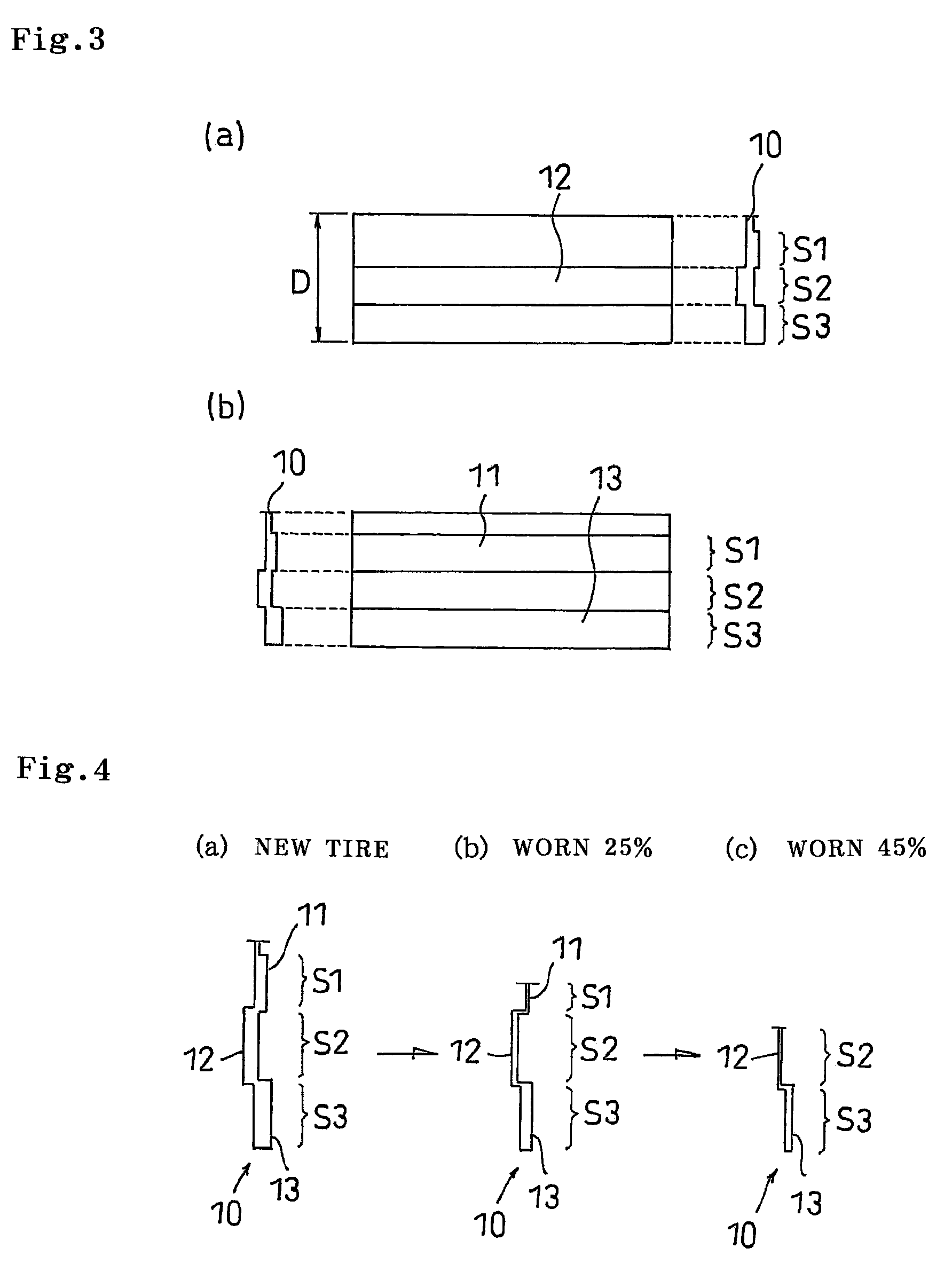
[0052]A description will be given below of an evaluation of an ice braking performance for specifically indicating the structure and the effect of the present invention. The ice braking performance is evaluated by installing the tire to an actual car (3000 cc class FR sedan) and measuring a braking distance at a time of traveling on an ice road surface and applying a braking force from a speed 40 km / h so as to actuate an ABS, and is evaluated in four stages including a state in which tires are new, worn 25%, worn 45% and worn 75%. A result of the comparative example at the state in which tires are new is indicated by an index 100, and the greater numerical value indicates the better ice braking performance.

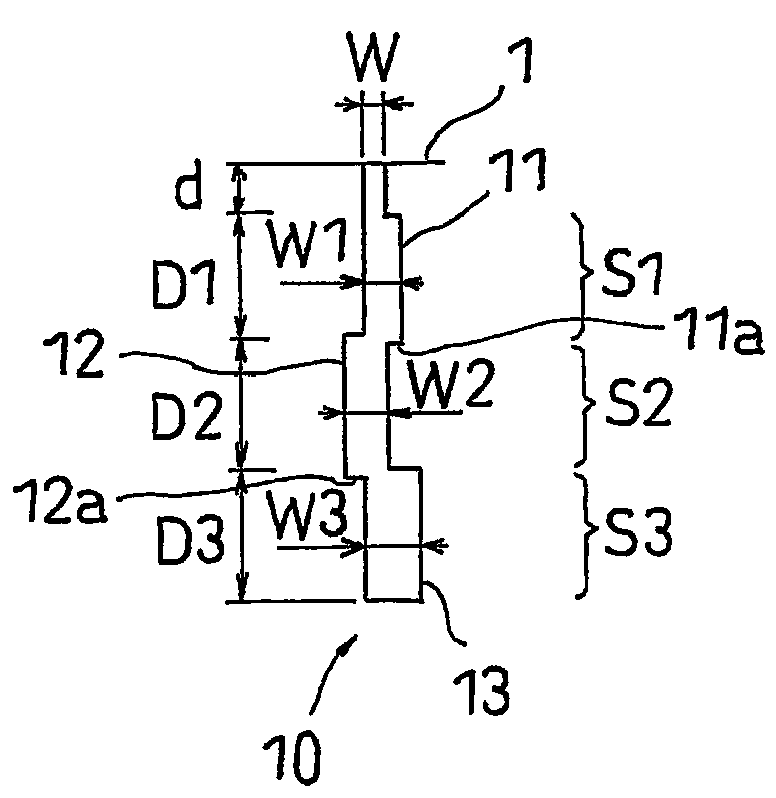
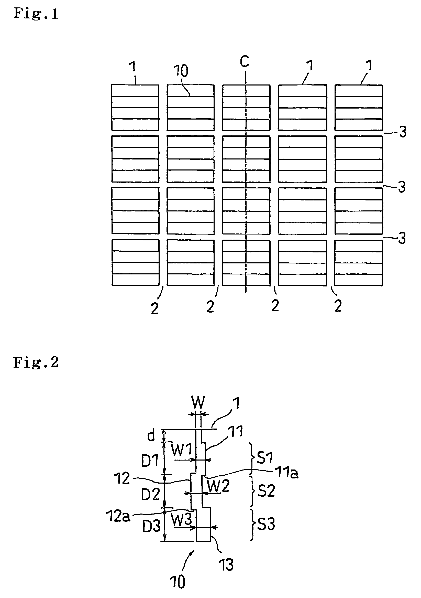
[0053]In the tire having the tread pattern as shown in FIG. 1, the tire having the fixed sipe width of 0.3 mm is set to the comparative example, and the tire having the sipe provided with the first to third sipe portions as shown in FIGS. 2 and 3 is set to the example. In the exam...


PUM


Abstract

A sipe formed in a block of a tread surface is provided with a first sipe portion having a first wide portion, a second sipe portion having a second wide portion in a different side from the first wide portion in a sipe width direction and positioned close to a sipe bottom portion side of the first sipe portion so as to become wider than the first sipe portion, and a third sipe portion having a third wide portion in the same side as the first wide portion in the sipe width direction and positioned close to a sipe bottom portion side of the second sipe portion so as to become wider than the second sipe portion.

Description

BACKGROUND OF THE INVENTION[0001]1. Field of the Invention[0002]The present invention relates to a pneumatic tire in which a sipe is formed in a land portion of a tread surface, and is particularly useful as a studless tire.[0003]2. Description of the Related Art[0004]Conventionally, in the studless tire, a cut called as the sipe is formed in the land portion of a block, a rib or the like, and a traveling performance on an ice road surface having a low friction coefficient is increased by an edge effect and a drainage effect generated by the sipe. As the sipe mentioned above, there have been put to a practical use a linear sipe extending linearly along a longitudinal direction, a waveform sipe extending like a waveform and the like.[0005]In this case, since a rubber is incompressible, a motion of the tread surface being in contact with the road surface becomes great in the case that a load is applied to the tire, so that an opening portion of the sipe tends to be closed. Particularl...

Claims


Application Information

Patent Timeline
Patent Type & Authority Patents(United States)
IPC IPC(8): B60C11/12
CPCB60C11/12B60C11/1218B60C11/1281B60C2011/1209
Inventor OHASHI, TOSHIYUKI
Owner TOYO TIRE & RUBBER CO LTD
Why Eureka
Try Eureka