

LED lighting device
a technology of led lighting and light source, which is applied in the direction of lighting support devices, point-like light sources, lighting and heating apparatus, etc., can solve the problems of cumbersome task of replacing light sources (fluorescent lamps), and achieve the effects of reducing power consumption, uniform illuminance distribution, and reducing the frequency of replacing light sources
- Summary
- Abstract
- Description
- Claims
- Application Information
AI Technical Summary
Benefits of technology
Problems solved by technology
Method used
Image

Examples
first embodiment
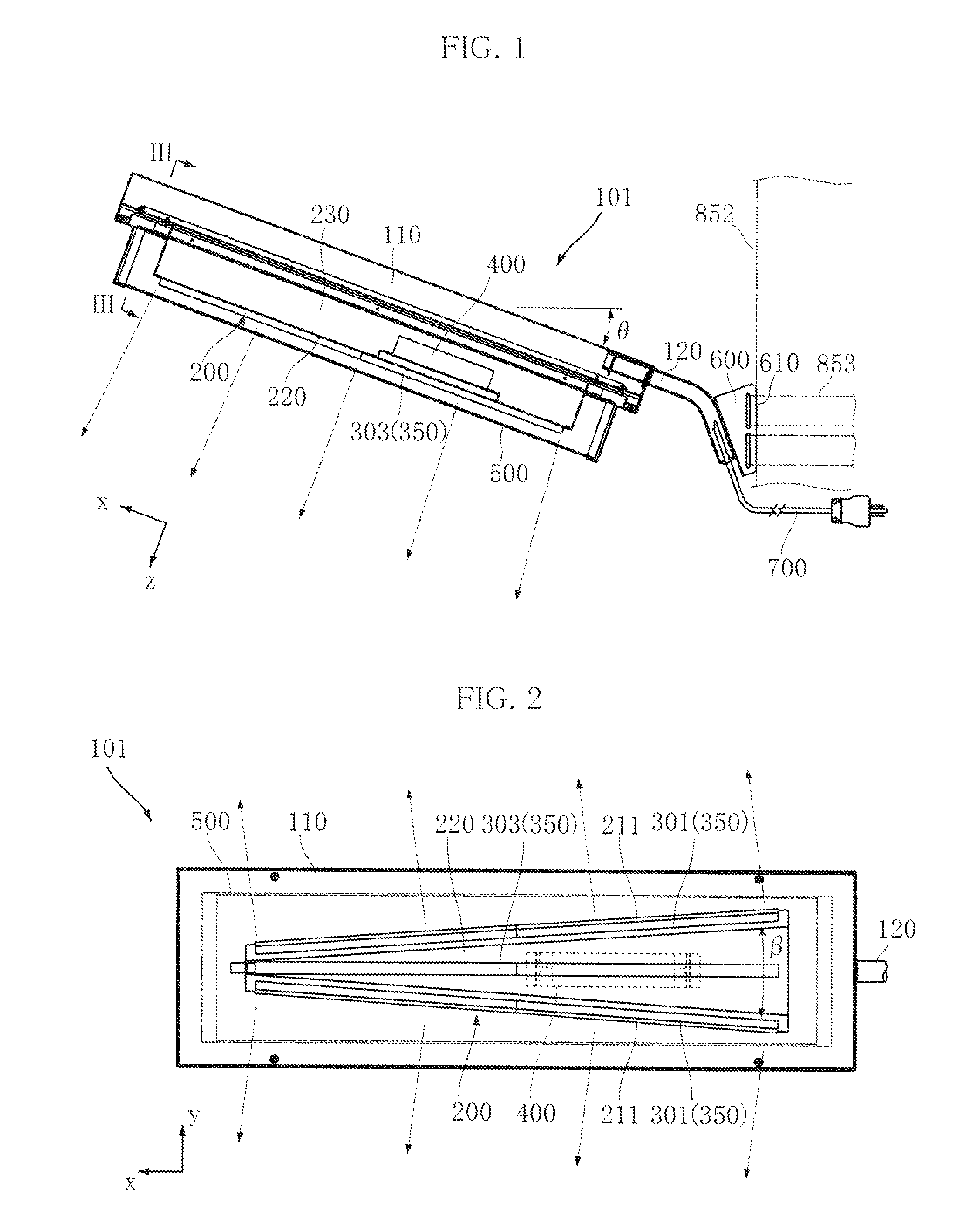
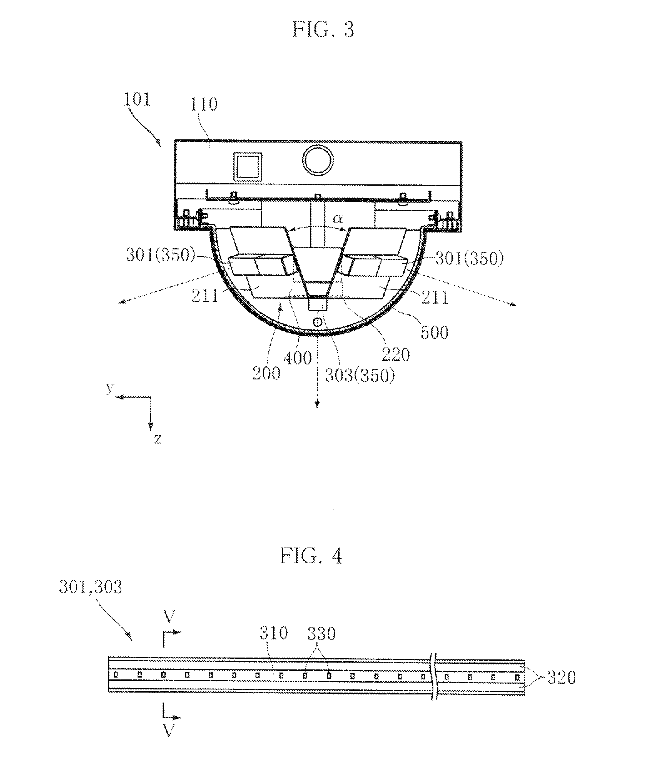
[0066]FIGS. 1 to 3 show an LED lighting device according to the present invention. An LED lighting device 101 according to the present embodiment includes a support bracket 110, a support arm 120, a mounting bracket 200, a pair of side LED units 301, a front LED unit 303, a power source unit 400, a light transmitting cover 500 and an attachment bracket 600. The LED lighting device 101 is used as, for example, a streetlight or a security light. In the present embodiment, the LED lighting device 101 has a length (x direction dimension) of approximately 700 mm (excluding the support arm 120), a width (y direction dimension) of approximately 200 mm and a height (z direction dimension) of approximately 140 mm.
[0067]The support bracket 110 supports the mounting bracket 200 and the light transmitting cover 500. The support bracket 110 has an elongated shape extending in the x direction, and it can be formed by, for example, bending a metal plate made of stainless steel having a thickness o...
second embodiment
[0090]FIGS. 12 to 14 show an LED lighting device according to the present invention. An LED lighting device 102 of the present embodiment is different from that of the above embodiment primarily in that a pair of side mounting faces 212 and a plurality of side LED units 302 are added.
[0091]In the present embodiment, a mounting bracket 200 has a pair of side mounting faces 211 and a pair of side mounting faces 212. The pair of side mounting faces 212 face mutually opposite sides in the y direction. The distance between the pair of side mounting faces 212 in the z direction becomes shorter from the back side (the upper side in FIG. 14) toward the front side (the lower side in FIG. 14). In the present embodiment, the angle α (see FIG. 3) between the pair of side mounting faces 212 in the yz plane is set to 38°. As shown in FIG. 13, the distance between the pair of side mounting faces 212 in the y direction becomes shorter from the base side in the x direction (the right side in the dia...
third embodiment
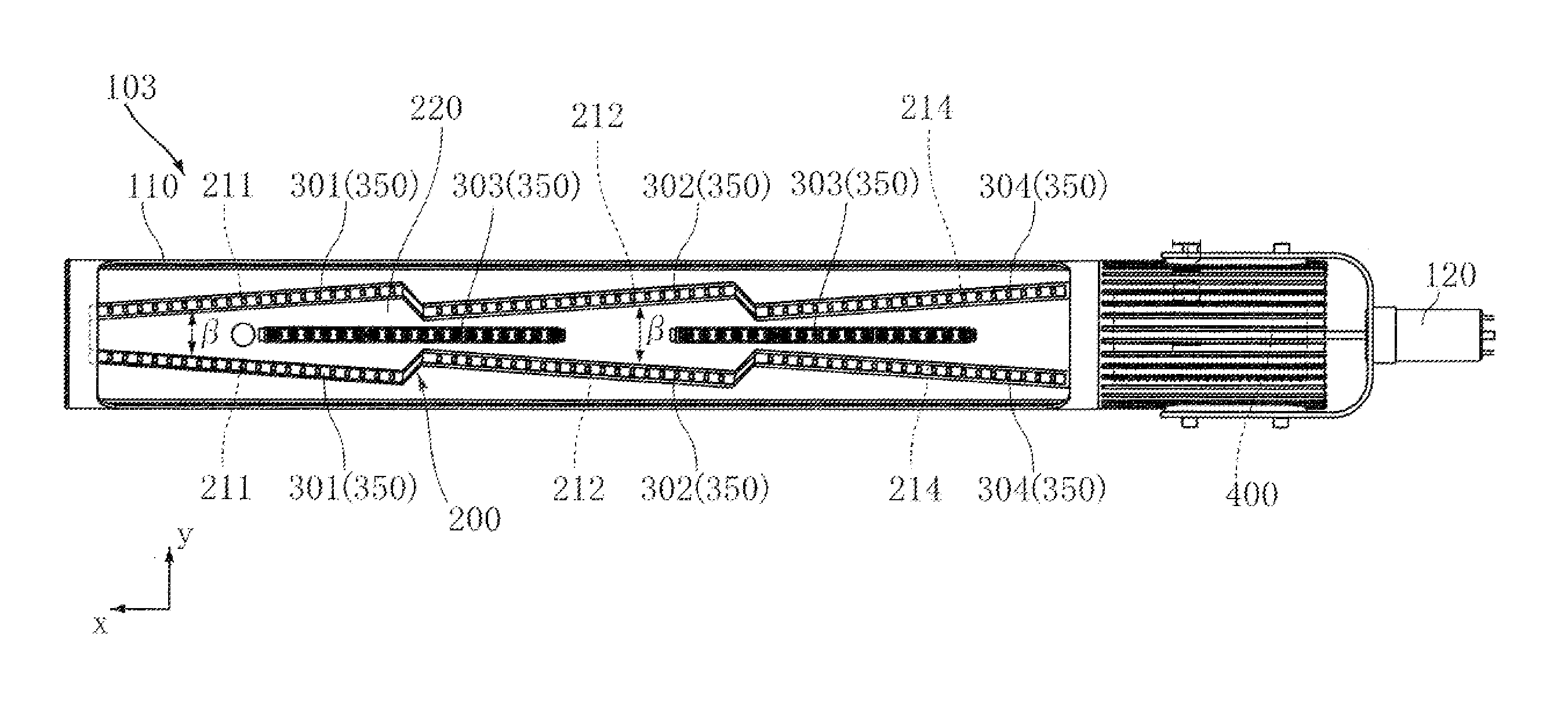
[0098]FIG. 15 shows an LED lighting device according to the present invention. An LED lighting device 103 of the present embodiment is different from that of the above-described embodiment in that it includes a pair of side mounting faces 214 and a pair of side LED units 304, and that the side LED units 301 and 302 have a configuration different from that of the above-described embodiment.
[0099]In the present embodiment, a pair of side mounting faces 214 is further provided on the base side in the x direction relative to the pair of side mounting faces 212. The dimensions of each of the side mounting faces 214 and their relative positional relationship are substantially the same as those of the pairs of side mounting faces 211 and 212.
[0100]In the present embodiment, as shown in FIG. 16, a series of side LED units 301, 302 and 304 is formed by a strip-shaped flexible wiring substrate 380 and a plurality of LED modules 330 mounted in a line on the substrate. The side LED unit 301 is ...
PUM
 Abstract
Description
Claims
Application Information