Water-saving lock configurations and operations

a technology of water-saving locks and configurations, applied in water installations, dry docks, construction, etc., can solve the problems of high cost, affecting shippers' shipping, and unused seagoing, so as to reduce salt intrusion volumes, reduce salt amount, and effectively counteract

Inactive Publication Date: 2013-10-01
SHELTON BERT GUSTAV
View PDF17 Cites 2 Cited by
  • Summary
  • Abstract
  • Description
  • Claims
  • Application Information

AI Technical Summary

Benefits of technology

[0022]3. Having a transiting vessel inside a chamber every time the chamber is to be filled or drained. Transiting a ship each time maximizes the service provided by the water that is used. To capitalize on this third water-saving method, it is necessary to change the canal's lock unit and channel system arrangement from the conventional and to define corresponding operating procedures.
[0035]Furthermore, separating steps also allows three methods for reducing the amount of salt that intrudes through locks to be combined. As is discussed in more detail later in this document, the more concentrated salt mixture that intrudes through locks when water is recycled to and from the chambers during ship-lifting operations can be more effectively counteracted by combining the three methods to reduced salt intrusion volumes than is possible with locks that are more conventionally arranged.

Problems solved by technology

Only about half the water that falls in the canal's watershed during the rainy season ends up used to lift or lower ships due to storage capacity limitations; some of the excess water is used to generate power, but much goes out to sea unused.
Panama Canal transit operations have been curtailed at least once when water was in short supply due to reduced rainfall, which was costly to shippers.
In addition to time and water-availability constraints that limit the amount of cargo that can be transited, two other present Panama Canal limitations that impact both world shipping and Panama's revenues are that: 1) ships larger than Panamax Class can't transit and 2) canal transits are sharply reduced when locks get overhauled.
However, other than tests of the method having been done under the Canal's US Administration, the method wasn't used, as shipping demands apparently did not exceed the system's water reserves with Madden Dam added.
Fewer transits and less revenue would have resulted from taking time to save water, only to dump it for lack of storage capacity.
The concern with the expansion of the Panama Canal is that the plan will add a relatively high-cost, low-return system that will cause excessive and unnecessary impact to third parties and to the environment ad infinitum.

Method used


Image

  • Water-saving lock configurations and operations
  • Water-saving lock configurations and operations
  • Water-saving lock configurations and operations

Examples


Embodiment Construction

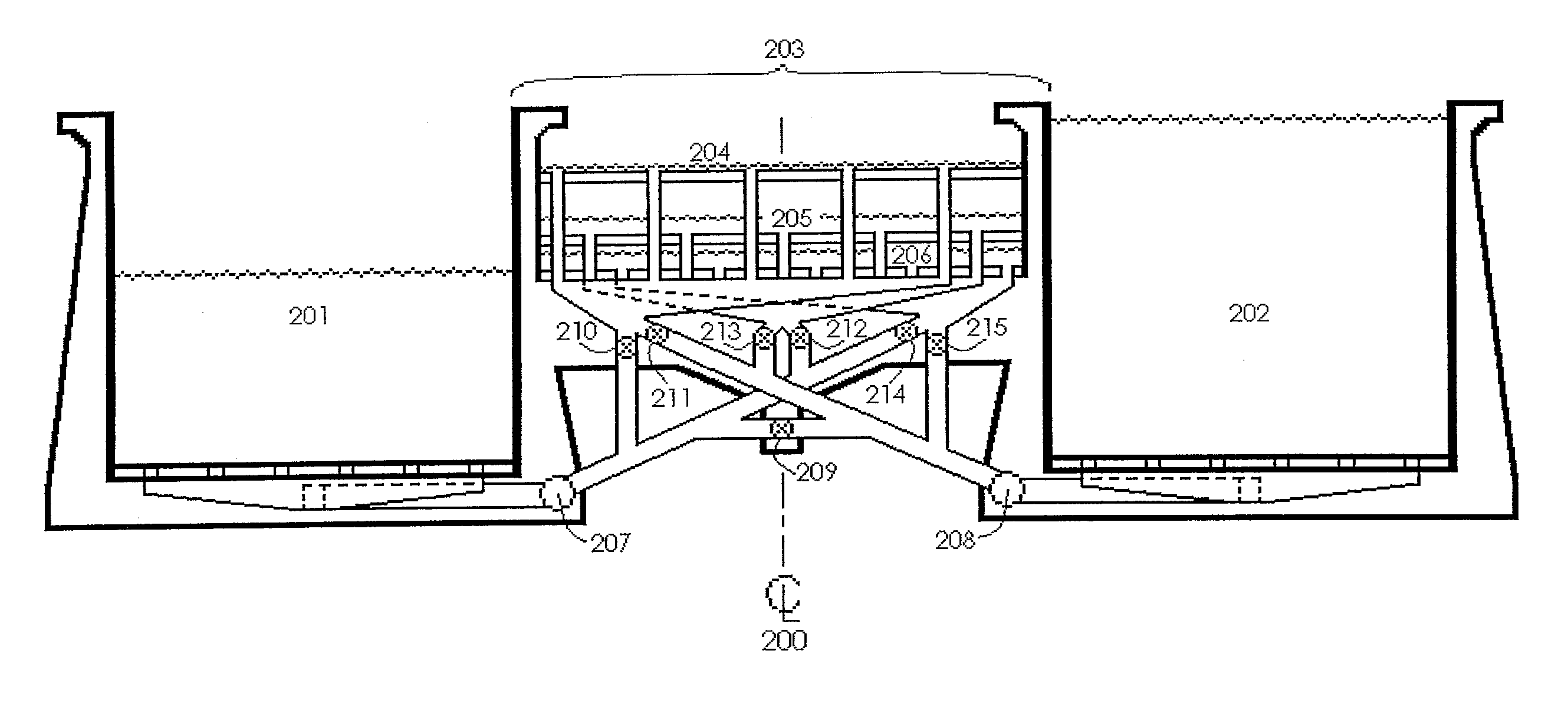
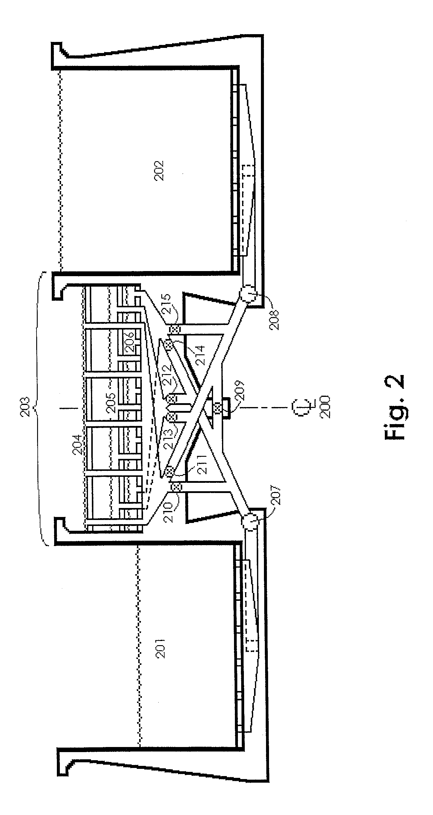
[0043]For the purpose of promoting an understanding of the principles of the inventions, reference will now be made to the embodiments illustrated in the drawings and specific language will be used to describe the same. It will nevertheless be understood that no limitation of the scope of the inventions is thereby intended, including such alterations and further modifications to the illustrated devices, and such further applications of the principles of the inventions as illustrated therein being contemplated, as would normally occur to one skilled in the art to which the inventions relate.

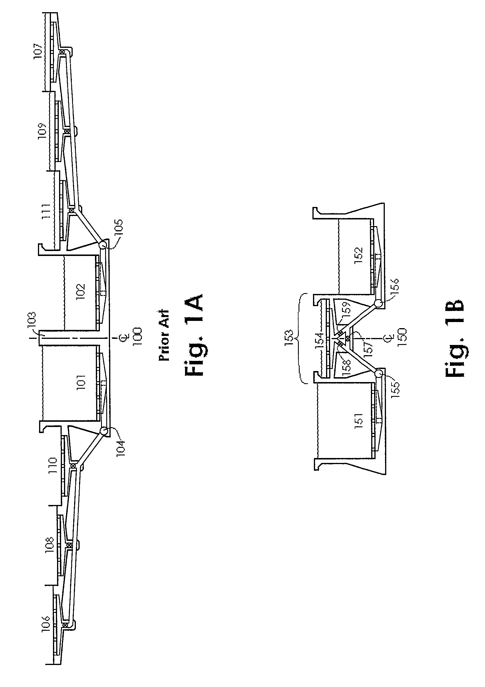
[0044]The devices, system arrangements, and operating methods described herein allow the water volume used by a hydraulic ship lift, commonly referred to as a lock, to be reduced in ways that differ with respect to how previously available lock designs were operated and in what could previously be done using system arrangements and operating methods applicable to the lock designs then available.

[0...


PUM


Abstract

A two-lane ship lock having center-wall tanks that hold water drained from one lane for use in filling the second lane as the unit is operated. The method reduces transit water-use where a lock connects a waterway to a sea with large daily tides by capturing seawater in a lagoon at high tide for use at start of chamber refilling during lower tides.

Description

REFERENCE TO RELATED APPLICATIONS[0001]This application claims the benefit of U.S. Patent Application Ser. No. 61 / 063,434, filed 4 Feb., 2008 and PCT / US2009 / 031539 filed 21 Jan. 2009, all of which is hereby incorporated by reference.BACKGROUND OF THE INVENTION[0002]1. Field of Invention[0003]The present inventions relate to designing and operating canal locks to lift and lower vessels, with emphasis on reducing per-transit water-use.[0004]2. Description of Prior Art[0005]A lock is a water-containment chamber—with sealing gates at each end—installed between a lower and an upper waterway. Water is either added to or removed from the chamber to respectively lift or lower the vessel or vessels floating in it. While the engineering, materials and construction of a lock's main components—its chambers, gates, pipes and valves—have notably improved over the millennia, it is still preferable to use gravity to move the water in and out of the lock chambers. Gravity flow has traditionally been...

Claims


Application Information

Patent Timeline
Patent Type & Authority Patents(United States)
IPC IPC(8): E02C1/00
CPCE03C1/02
Inventor SHELTON, BERT GUSTAV
Owner SHELTON BERT GUSTAV
Why Eureka
Try Eureka