
Organic light emitting display apparatus and method of driving the same

a technology of light-emitting display and apparatus, which is applied in the direction of instruments, static indicating devices, electroluminescent light sources, etc., can solve the problems of large power consumption, short driving (or light-emitting) time of each light-emitting device, and long driving (or light-emitting) time, so as to minimize power consumption, reduce or remove motion blurring, and reduce brightness. the effect of reducing or removing the effect of brightness reduction

Active Publication Date: 2013-10-01
SAMSUNG DISPLAY CO LTD
View PDF11 Cites 2 Cited by
  • Summary
  • Abstract
  • Description
  • Claims
  • Application Information

AI Technical Summary

Benefits of technology

[0013]Aspects of the present invention are directed to an organic light emitting display apparatus which can minimize brightness reduction, minimize an increase in power consumption, and reduce or remove motion blurring, and a method of driving the organic light emitting display apparatus.

Problems solved by technology

However, an organic light emitting display apparatus operated using the passive matrix method consumes large amounts of power when used to drive a large screen, and a driving (or light emitting) time of each light emitting device is short.
An organic light emitting display apparatus operated using the active matrix method consumes small amounts of power and has a long driving (or light emitting) time.
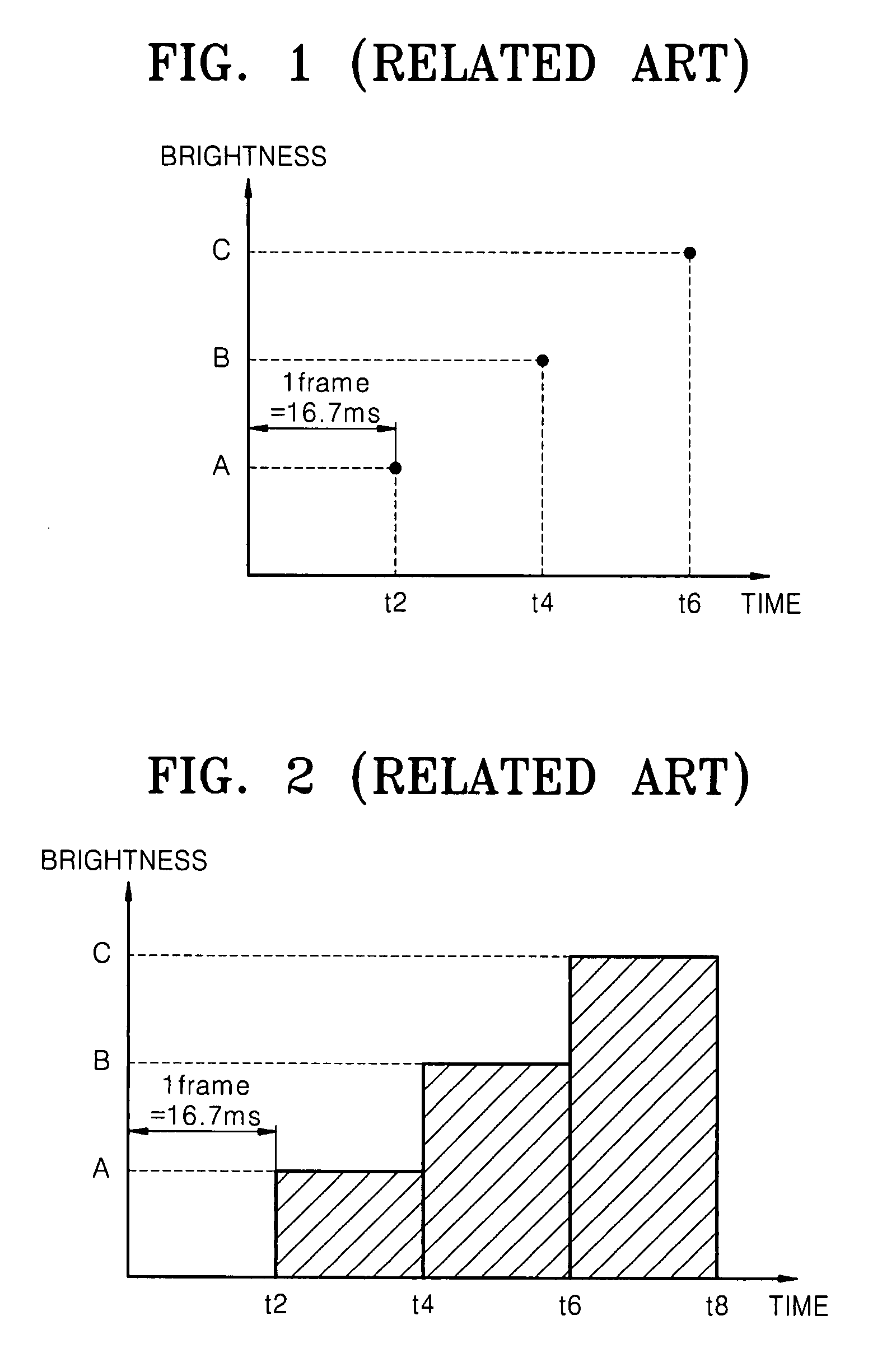
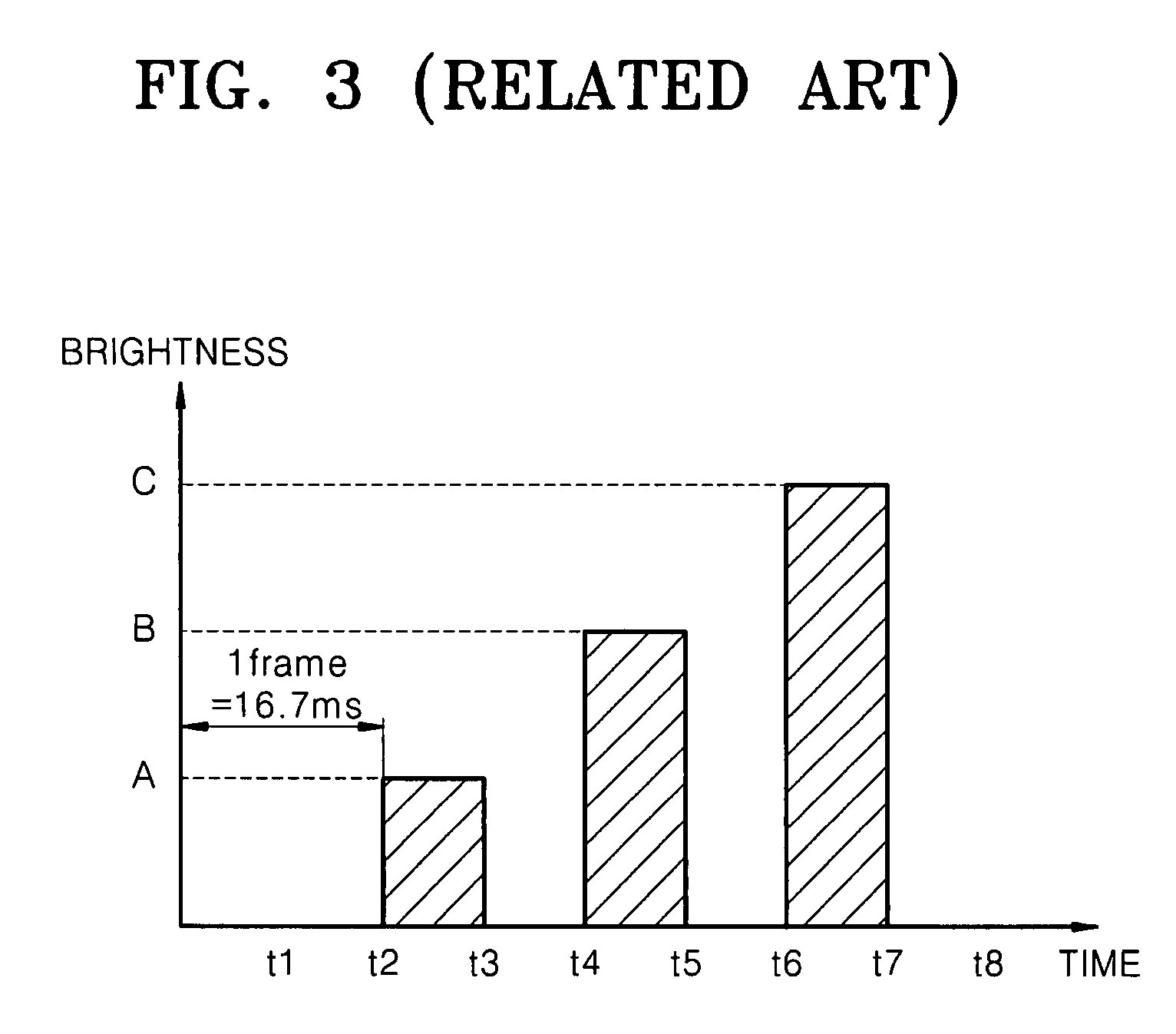
However, the organic light emitting display apparatus operated using the active matrix method has a motion blurring problem.
However, such a driving method suffers from a reduction in an average brightness of the entire screen by the amount of the inserted black frame images.
However, increasing current flow increases power consumption.

Method used


Image

  • Organic light emitting display apparatus and method of driving the same
  • Organic light emitting display apparatus and method of driving the same
  • Organic light emitting display apparatus and method of driving the same

Examples


Embodiment Construction

[0049]Reference will now be made in detail to aspects of the present invention, examples of which are illustrated in the accompanying drawings, wherein like reference numerals refer to the like elements throughout. The aspects are described below in order to explain the present invention by referring to the figures.

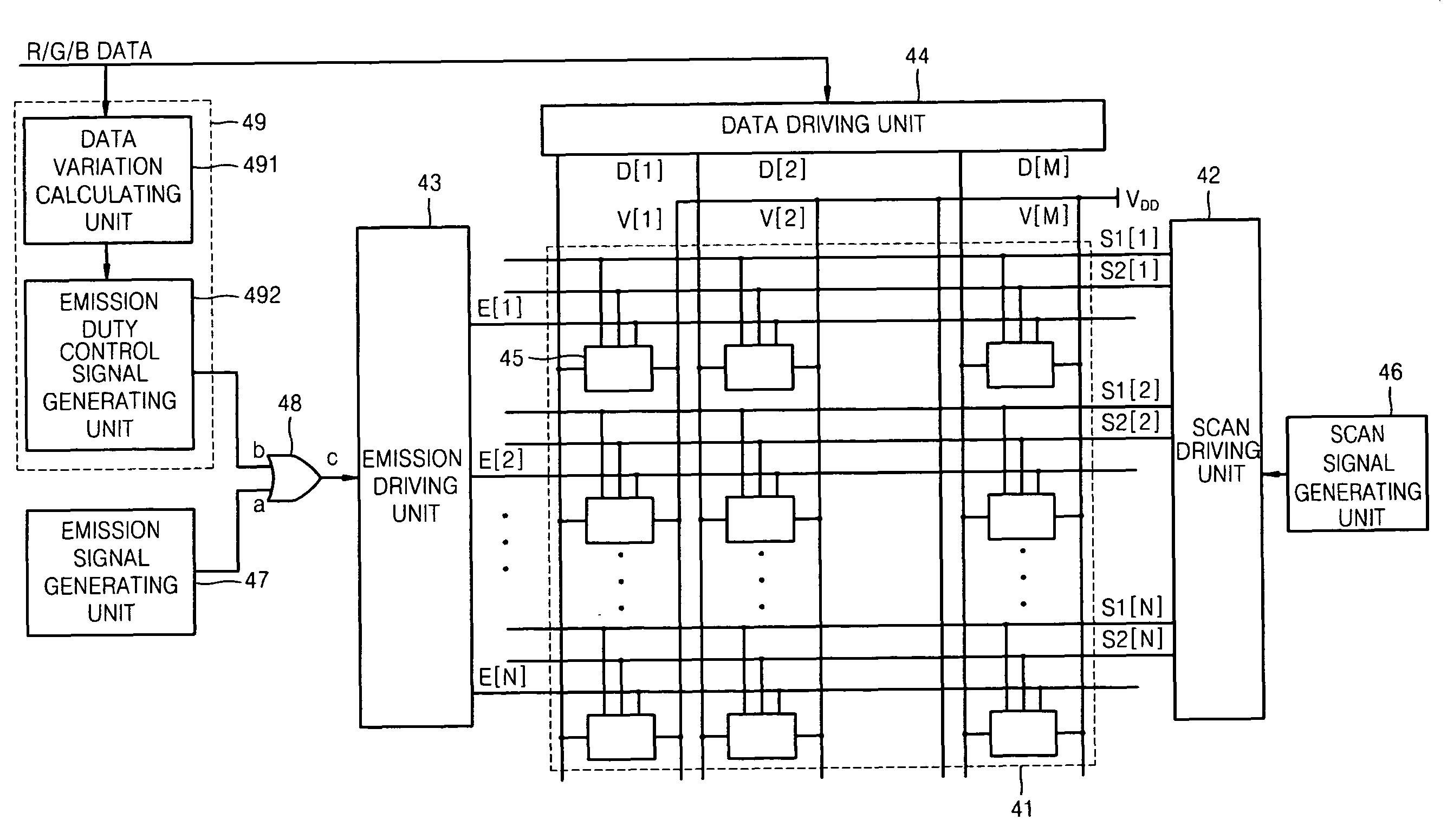
[0050]FIG. 4 is a block diagram of an organic light emitting display apparatus according to an aspect of the present invention. Referring to FIG. 4, the organic light emitting display apparatus includes an image displaying unit 41, a scan driving unit 42, an emission driving unit 43, a data driving unit 44, a scan signal generating unit 46, an emission signal generating unit 47, an OR gate 48, and an emission duty controlling unit 49.

[0051]The image displaying unit 41 includes N×M pixels 45, N first scan lines S1[1] through S1[N], N second scan lines S2[1] through S2[N], and N emission scan lines E[1] through E[N] formed in a row direction, M data lines D[1] through D[M],...


PUM


Abstract

An organic light emitting display apparatus minimizes brightness reduction and power consumption increase, and can remove motion blurring. The organic light emitting display apparatus includes a plurality of pixels, each including an organic light emitting device and a pixel circuit, a data driving unit to apply a data signal to data lines connected to the pixels, a scan driving unit to apply a selection signal to selection scan lines connected to the pixels, an emission signal generating unit to generate a first emission signal, an emission duty controlling unit to calculate basic information to reduce motion blurring and to generate an emission duty control signal based on the basic information, a logic gate to output a second emission signal by receiving the first emission signal and the emission duty control signal, and an emission driving unit to apply the second emission signal to emission scan lines connected to the pixels.

Description

CROSS-REFERENCE TO RELATED APPLICATION[0001]This application claims the benefit of Korean Application No. 2006-90145, filed on Sep. 18, 2006 in the Korean Intellectual Property Office, the disclosure of which is incorporated herein by reference.BACKGROUND OF THE INVENTION[0002]1. Field of the Invention[0003]Aspects of the present invention relate to an organic light emitting display apparatus which can minimize brightness reduction, minimize an increase in power consumption, and reduce or remove motion blurring, and a method of driving the organic light emitting display apparatus.[0004]2. Description of the Related Art[0005]In general, light emitting display apparatuses display images using self-emissive devices. Such light emitting display apparatuses are classified into inorganic light emitting display apparatuses having a light emitting layer formed of an inorganic material, and organic light emitting display apparatuses having a light emitting layer formed of an organic material...

Claims


Application Information

Patent Timeline
Patent Type & Authority Patents(United States)
IPC IPC(8): G09G3/30H05B44/00
CPCG09G3/2014G09G3/3233G09G2300/0819G09G2300/0852G09G2300/0861G09G2320/0261G09G2320/106G09G2330/021G09G2360/144G09G2360/16
Inventor KIM, HYEONG-GWON
Owner SAMSUNG DISPLAY CO LTD
Learn More