System for providing a transducer having a main coil and an additional coil separated from the main pole by a write shield

a technology of write shield and transducer, which is applied in the direction of magnetic recording head, data recording, instruments, etc., can solve the problems of inability to write at higher data rates, and inability to achieve high data rates

Active Publication Date: 2013-10-01
WESTERN DIGITAL TECH INC
View PDF35 Cites 163 Cited by
  • Summary
  • Abstract
  • Description
  • Claims
  • Application Information

AI Technical Summary

Problems solved by technology

Although the conventional transducer 10 may function, it may not be effective at higher data rates.
Thus, the write shield may not be driven at sufficiently high data rates by the coil 20.
As a result, the transducer 10 may not be capable of writing at higher data rates.
Thus, performance of the conventional transducer 10 may degrade.

Method used


Image

  • System for providing a transducer having a main coil and an additional coil separated from the main pole by a write shield
  • System for providing a transducer having a main coil and an additional coil separated from the main pole by a write shield
  • System for providing a transducer having a main coil and an additional coil separated from the main pole by a write shield

Examples


Embodiment Construction

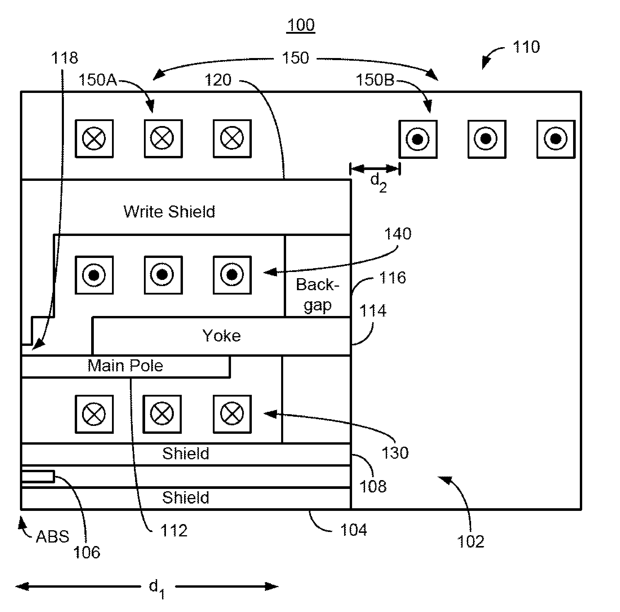
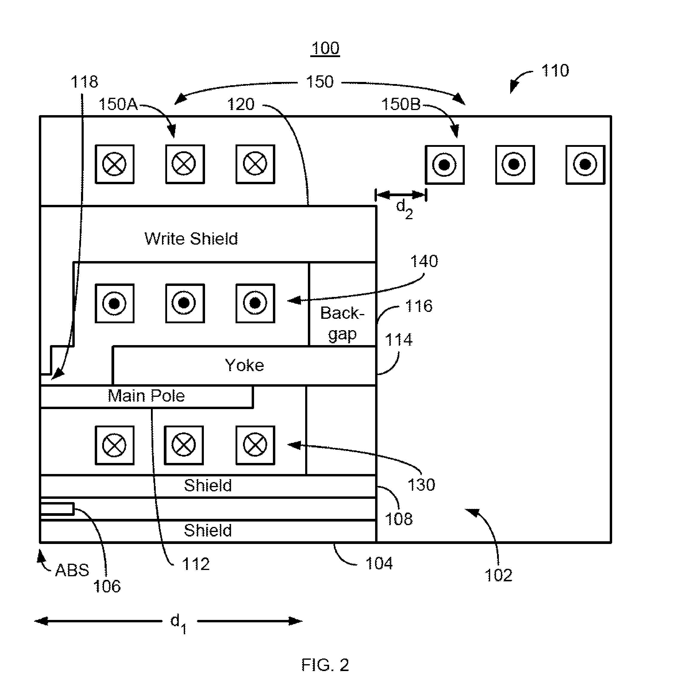
[0015]FIG. 2 is a diagram depicting a side view of a portion of a magnetic recording head 100 that may reside on a slider (not shown) in a disk drive that also include media (not shown). For clarity, FIG. 2 is not to scale. For simplicity not all portions of the head 100 are shown. In addition, although the head 100 is depicted in the context of particular components other and / or different components may be used. Further, the arrangement of components may vary in different embodiments. The head 100 has an ABS configured to reside close to a media (not shown) during operation. The head 100 is a merged head including a read transducer 102 and a write transducer 110. The read transducer 102 includes shields 104 and 108 as well as read sensor 106. In other embodiments, the head 100 may include only the transducer 110.

[0016]The write transducer 110 may be considered to include the shield 108. In addition, the transducer 110 includes main pole 112, yoke 114 (otherwise known as an auxiliar...


PUM

PropertyMeasurementUnit
lengthaaaaaaaaaa
lengthaaaaaaaaaa
lengthaaaaaaaaaa

Abstract

A method and system for providing a magnetic recording head is described. The magnetic recording head has an air-bearing surface (ABS) configured to reside in proximity to a media during use. The head includes a first coil, a second coil, a main pole, and a third coil. The first coil has a first plurality of turns and is configured to carry a first write current in a first direction. The second coil has a second plurality of turns and is configured to carry a second write current in a second direction. The main pole is between the first coil and the second coil. The third coil has a third plurality of turns configured to carry a third write current in a third direction.

Description

BACKGROUND[0001]FIG. 1 depicts a portion of a conventional magnetic recording transducer 10. For clarity, FIG. 1 is not to scale. The conventional transducer 10 includes a shield 12, main pole 14, yoke 16 (otherwise termed an auxiliary pole), coils 18 and 20, write shield / return pole 22 and back gap 24. The coils 18 and 20 may together form a helical coil. Alternatively, each coil 18 and 20 may be a pancake coil and have a second set of turns (not shown) further from the ABS. Although depicted as above the main pole 14 (with respect to the substrate that is not shown), the yoke 16 might be below the main pole 14. In operation, a current is driven through the coil(s) 18 and 20 to energize the main pole 14. As a result, the main pole 14 writes to the media (not shown).[0002]Although the conventional transducer 10 may function, it may not be effective at higher data rates. The trend in magnetic recording is to higher areal densities and higher data rates. In the conventional transducer...

Claims


Application Information

Patent Timeline
Patent Type & Authority Patents(United States)
IPC IPC(8): G11B5/127G11B5/17
CPCG11B5/3116G11B5/3123G11B5/17
Inventor BAI, ZHIGANGLI, ZHANJIEBATRA, SHARAT
Owner WESTERN DIGITAL TECH INC
Why Eureka
Try Eureka