Hollow wheel set

a technology of hollow wheels and wheel racks, which is applied in the direction of castors, vehicle components, domestic applications, etc., can solve the problems of increasing the number of elements used, increasing the production cost of the wheel racks, and complicated overall structure, so as to reduce the overall weight

Active Publication Date: 2013-10-08
WU NA
View PDF13 Cites 22 Cited by
  • Summary
  • Abstract
  • Description
  • Claims
  • Application Information

AI Technical Summary

Benefits of technology

[0007]In view of the problems and shortcomings of the prior art, the present invention p...

Problems solved by technology

However, in such a design structure, the use of a pair of fixing arms 12 will make the production cost of the wheel rack 10 rather high.
Moreover, the approach of using the fixing piece 22 having locking threads to lock and fix with the positioning pi...

Method used


Image

  • Hollow wheel set
  • Hollow wheel set
  • Hollow wheel set

Examples


Embodiment Construction

[0020]The purpose, construction, features, functions and advantages of the present invention can be appreciated and understood more thoroughly through the following detailed description with reference to the attached drawings. And, in the following, various embodiments are described in explaining the technical characteristics of the present invention.

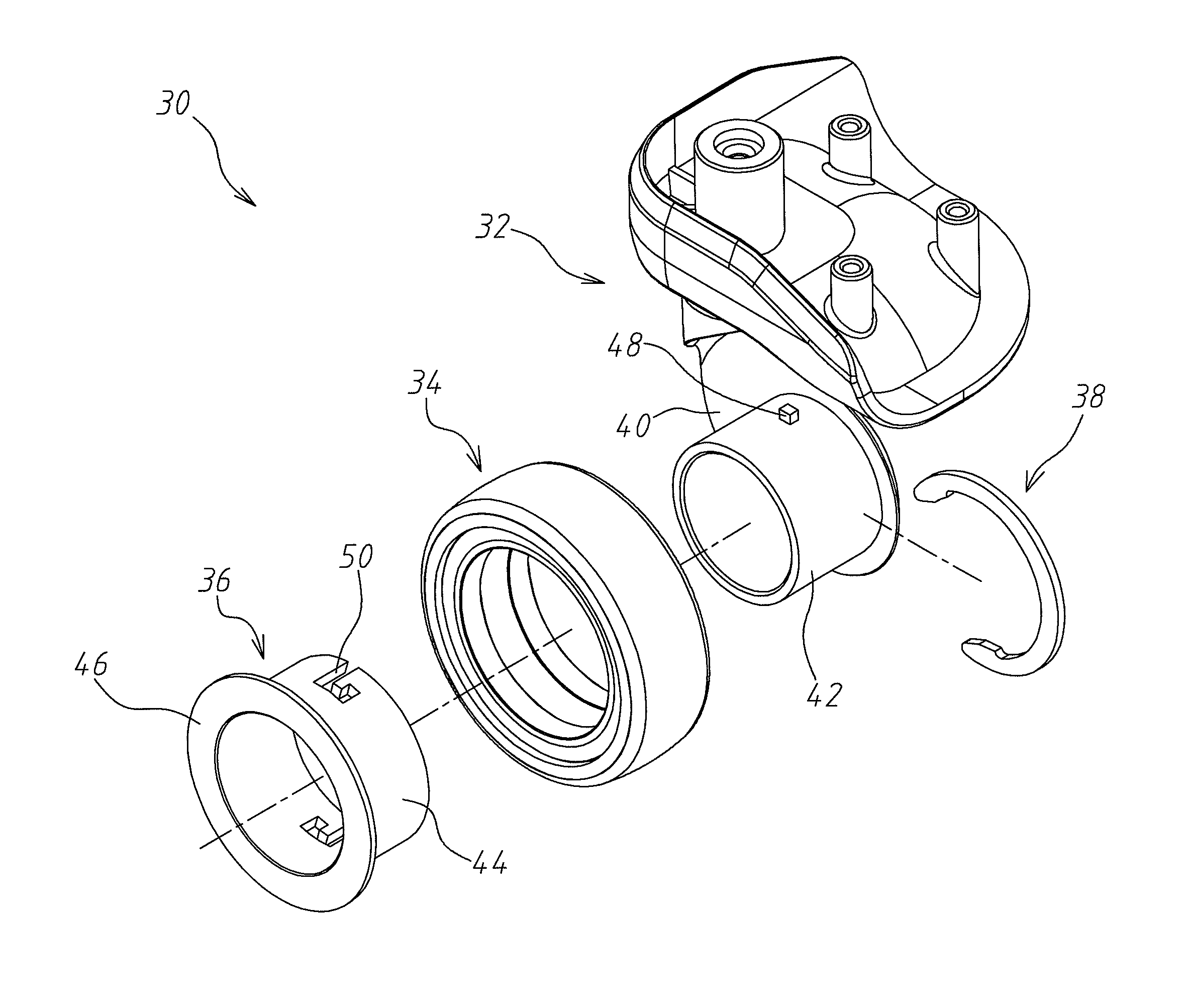
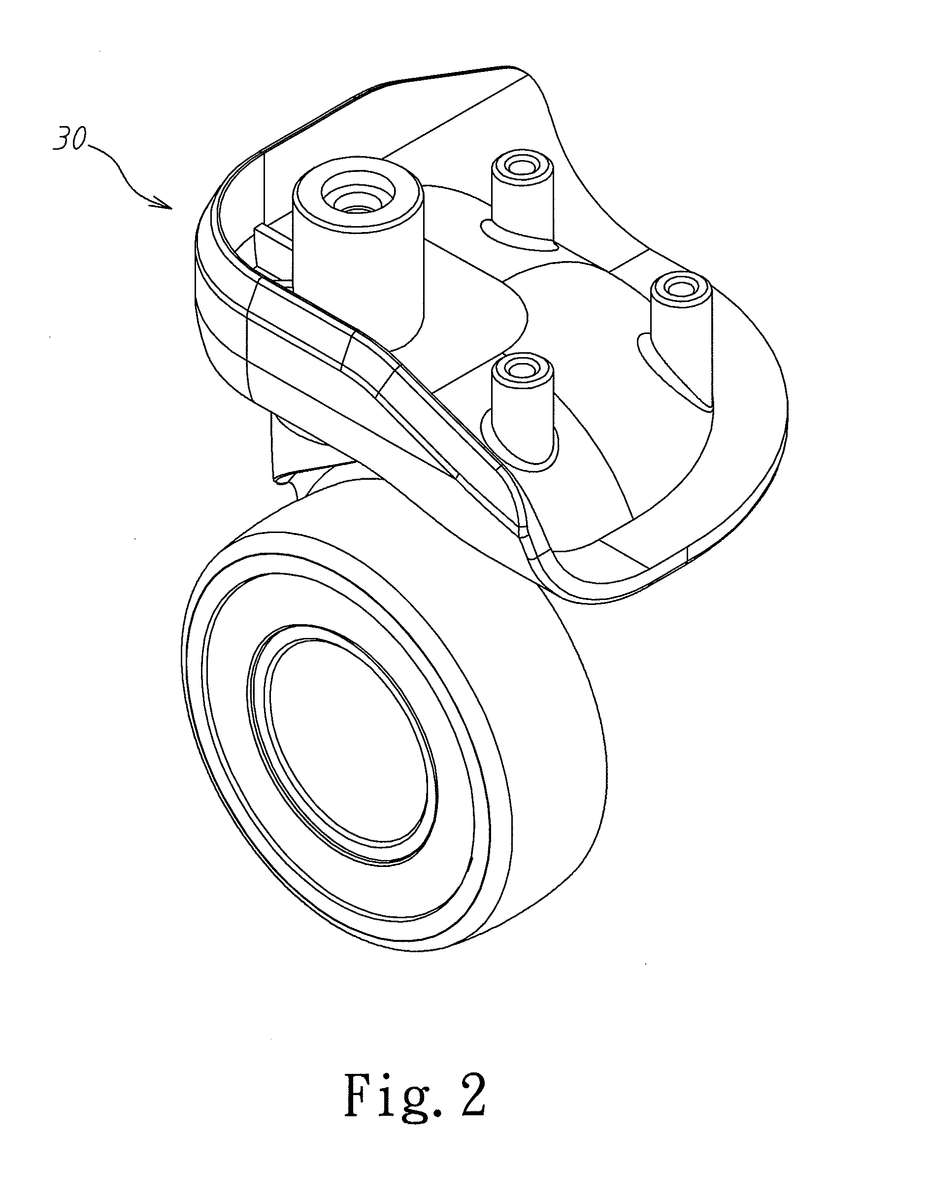
[0021]Refer to FIGS. 2, 3, 4, and 5 respectively for a perspective view, an exploded view of a part of elements, an exploded view of elements, and a cross section view of a hollow wheel set according to the present invention. As shown in FIGS. 2, 3, 4, and 5, the hollow wheel set 30 of the present invention mainly includes a a wheel rack 32, a hollow rotation wheel 34, a restricting sleeve 36, and a restricting and fastening ring 38. The wheel rack 32 includes a fixing arm 40, on a side wall of the fixing arm 40 is provided with a wheel fork 42. The hollow rotation wheel 34 is sleeved onto the wheel fork 42. One end of the restricting s...


PUM


Abstract

A hollow wheel set, comprising mainly a wheel rack, a hollow rotation wheel, a restricting sleeve, and a restricting and fastening ring. The wheel rack includes a fixing arm, on said fixing arm is provided with a wheel fork. The hollow rotation wheel is sleeved onto the wheel fork. One end of the restricting sleeve is a sleeve connection portion, while the other end is a ring-shape blocking portion. The sleeve connection portion is sleeved and fixed on the outer perimeter of the wheel fork, and is located between the wheel fork and the hollow rotation wheel. The ring-shape blocking portion is on a side of the hollow rotation wheel. The restricting and fastening ring is fastened around outer perimeter of the wheel fork, and is locate on the other side of the hollow rotation wheel, to reduce size and weight of the hollow wheel set.

Description

BACKGROUND OF THE INVENTION[0001]1. Field of the Invention[0002]The present invention relates to a wheel set structure, and in particular to a hollow wheel set structure without the conventional wheel axis, so as to reduce its weight.[0003]2. The Prior Arts[0004]Presently on the market, a kind of wheel set is available for being installed at the bottom of the main body in the following approach to carry weight: a wheel rack 10 having a connection seat 14 and a pair of fixing arms 12 are provided, to match with a wheel 18 with its center having a wheel axis 16, and a through hole 20 is disposed through the pair of fixing arms 12, as shown in FIG. 1. The connection of the wheel 18 and the pair of fixing arms 12 is achieved through using a fixing piece 22 to run through the through hole 20 and wheel 18, and then it is locked and fixed with a positioning piece 24.[0005]However, in such a design structure, the use of a pair of fixing arms 12 will make the production cost of the wheel rac...

Claims


Application Information

Patent Timeline
IPC IPC(8): A47B91/06B60B33/00
CPCA47B91/06B60B33/00B60B33/0028B60B37/10A45C2005/148B60B33/0039B60B33/0049B60B33/0057B60B33/0068B60B33/0076B60B2200/45B60B2900/111B60B2900/113B60B2900/115
Inventor WU
Owner WU NA
Why Eureka
Try Eureka