Multiple tablet cutter

a tablet cutter and multi-tablet technology, applied in metal-working equipment, thin material processing, metal-working equipment, etc., can solve the problems of limited device availability, pad supply, and difficulty in supplying pads

Active Publication Date: 2013-10-08
RAGHUPRASAD PUTHALATH KOROTH
View PDF28 Cites 12 Cited by
  • Summary
  • Abstract
  • Description
  • Claims
  • Application Information

AI Technical Summary

Problems solved by technology

Each of these pill cutter or pill splitter devices has a limitation as it can handle only one pill at a time.
When a patient needs to cut a plurality of pills or more than one pill, very few devices are available.
A disadvantage of this design is that to provide different sizes, different pads have to be provided with different hole sizes.
Therefore, the device is limited to one particular size pill.
Accordingly, while this device achieves the goal of cutting simultaneously as many as 30 pills, it does so in such a fashion that it is limited to one particular size per cut and further by the fact that it can only cut the pills in half.
This device is further limited by the fact that it requires a rather strong uniform pressure to achieve a desired breaking of all the pills.
The drawback of this particular automated device is likely expensive and is ideally suited mainly for a pharmaceutical company as opposed to an individual patient or pharmacy.

Method used


Image

  • Multiple tablet cutter
  • Multiple tablet cutter
  • Multiple tablet cutter

Examples


first embodiment

[0042]With reference to FIG. 11A, the device 100 is shown where the upper portion of the housing 150 is in the unloaded stowed position wherein the coil springs 600 are fully extended in the upper portion of the housing as illustrated. In this embodiment, the upper portion of the housing 150 has a guide support structure 300 made as an integral portion to the upper portion 150 of the housing structure 120. In this fashion the blades 320 are mounted directly into the support structure 300 in such a fashion that they align with the slots 720 on the lower portion 160 of the housing. Around the outer periphery of the support structure 300 is shown a channel 190. The channel 190 provides a guide for the lower portion 160 to pass. Around the peripheral edge of the lower portion 160 are protruding sides 165, which upon compression of the springs 600 extend into the channels 190 as illustrated in FIG. 11B. Therefore, the entire tablet-cutting device 100 is essentially made with two moving c...

third embodiment

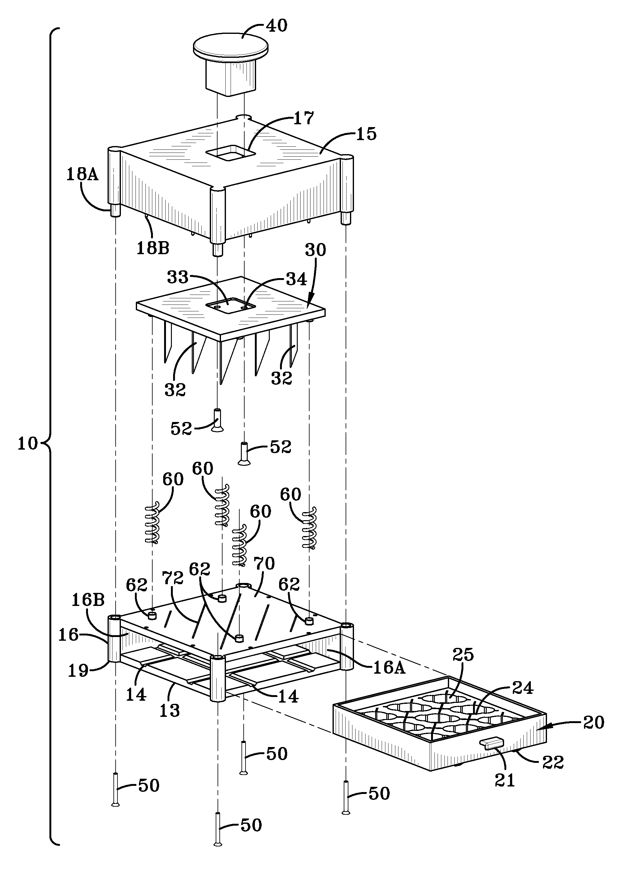
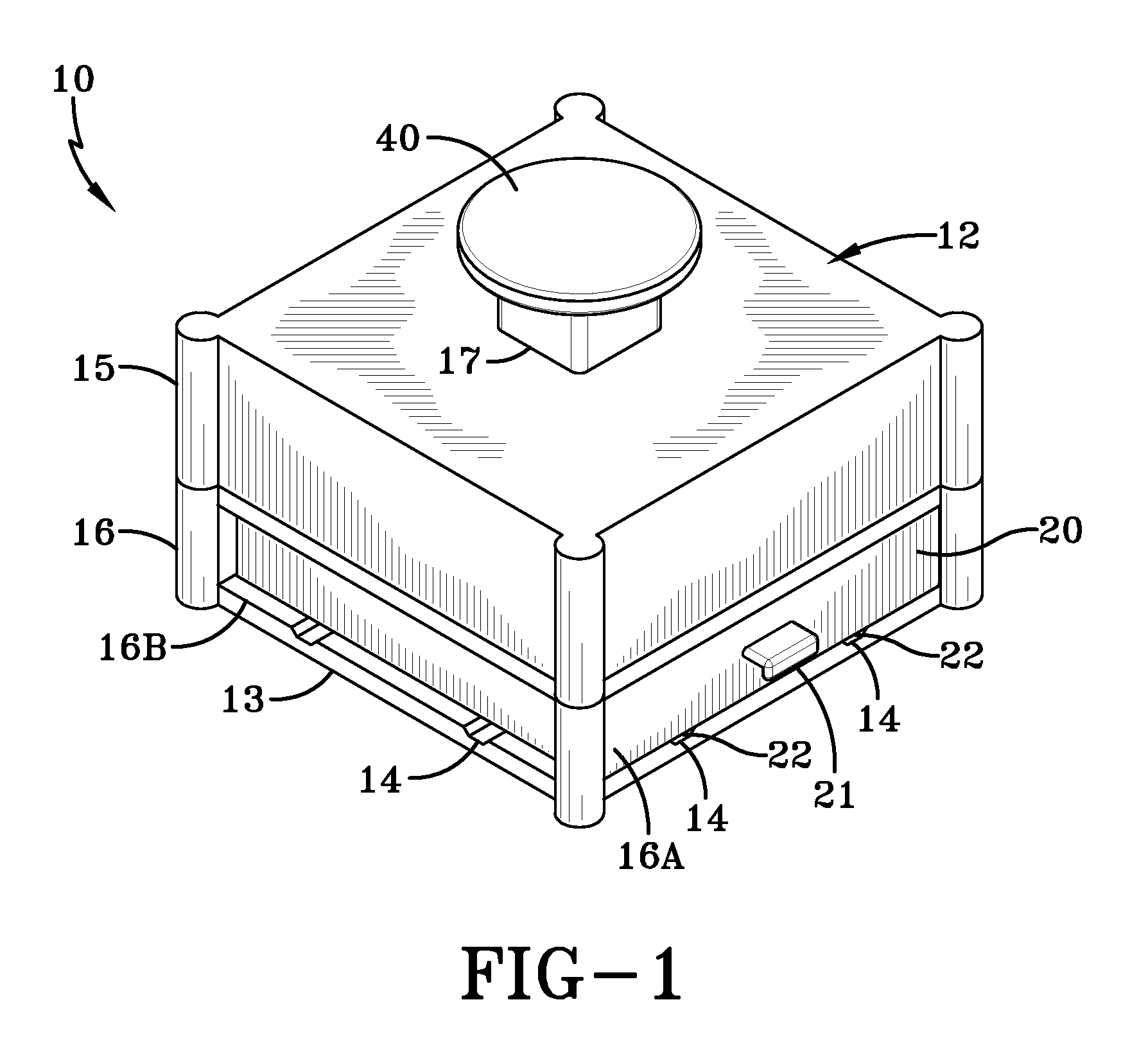
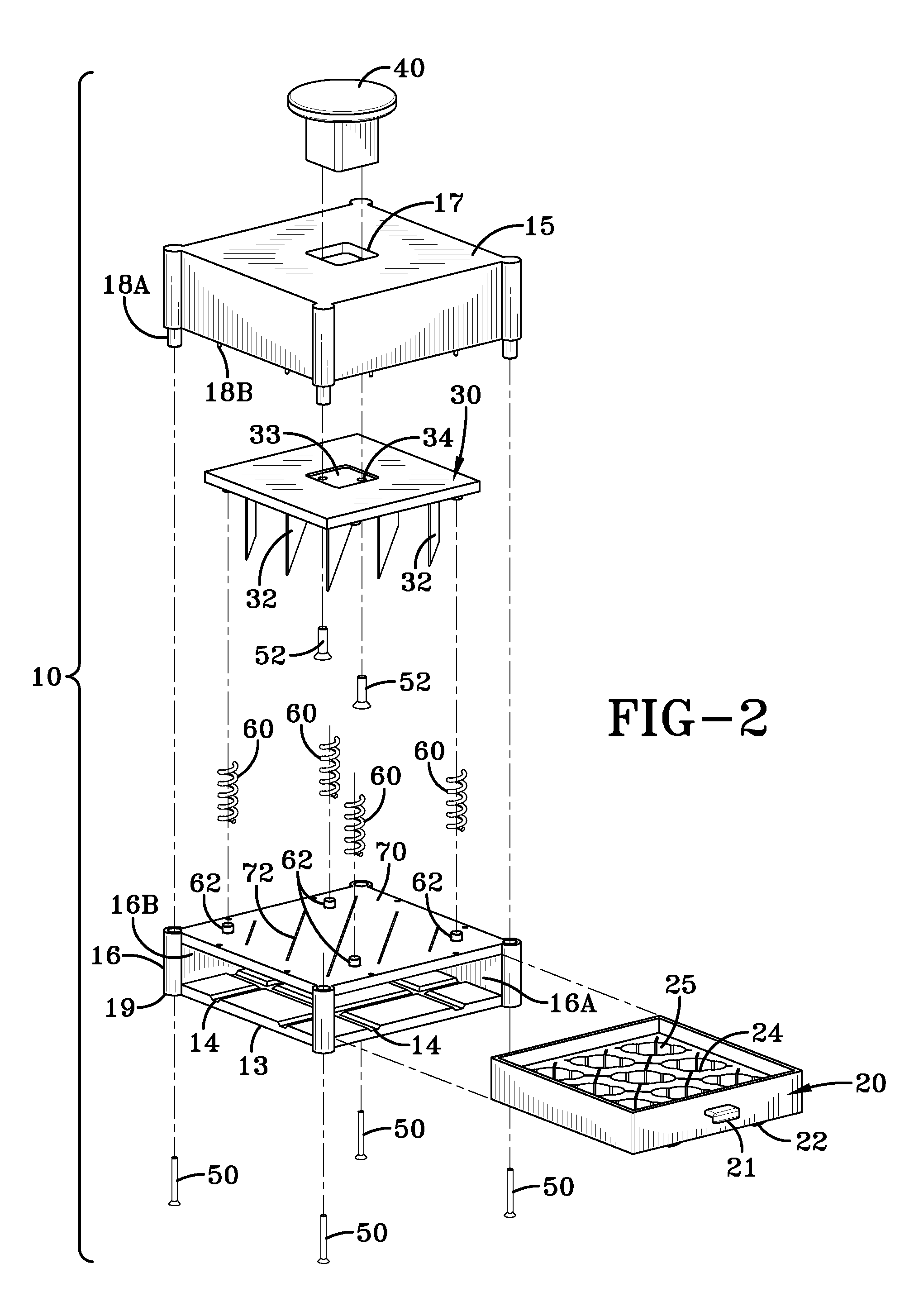
[0045]With reference to FIG. 13, a cross sectional view of the third embodiment made according to the present invention, is illustrated. In this embodiment, the housing structure 12′ is designed so that the upper housing portion 15′ containing the blade support structure 30′ and blades 32′. The blade support structure 30′ and blades 32′ are housed in the upper housing portion 15′ and the chopper handle 40′ is secured to the support structure 30′ and is moveable within the hole 17′ using a compression spring 60′ to hold the blades 32′ in a retracted position except during the process of cutting the pills. As illustrated, the lower housing portion 16′ holds the removable tray 20′ in such a fashion that the nests 25′ are aligned with the blades 32′. Guides 80′ and 82′ in the lower housing 16′ are aligned with openings 70′ and 72′ in the upper housing 15′ such that when the blades 32′ are in the retracted position they clear the lower housing 16′ completely but are still guided by slots...


PUM


Abstract

A multi-tablet cutting device has a removable tablet holding tray, a housing structure and a plurality of vertically movable cutting blades. The removable tablet holding tray has a plurality of tablet nests. Each nest has two or more levels of beds sized to hold tablets of different sizes or shapes. The housing structure has at least one opening to receive the removable tablet holding tray. The plurality of vertically movable cutting blades is mounted on a support structure on the inside of the housing above the tablet holding tray above a location where the tablet holding tray is stored. The plurality of cutting blades is aligned above the tablet nests and upon a downwardly directed vertical movement the plurality of cutting blades passes through first slots in the nests aligned with the cutting blades to cut the tablets held in the nests into halves.

Description

TECHNICAL FIELD[0001]This invention relates an improved pill or tablet cutter device and more particularly to a tablet cutter for simultaneously cutting a plurality of pills. More specifically it relates to a tablet cutter which can simultaneously cut a plurality of tablets of different sizes.BACKGROUND OF THE INVENTION[0002]Medicines can be delivered in the shape of a pill or tablet. These pills or tablets provide a dosage of medicine that can be administered to the patient. Oftentimes the amount contained in the tablet is more than is required for a patient and in order to get the proper dosage it is convenient to split the tablet in half or even quarters. Oftentimes the individual patient is requested to split his own medicine dosage of tablets to the proper dosage. To achieve this, a variety of pill cutters have been provided, almost all are designed to cut a single pill of a particular size. Some of these are described in U.S. Pat. Nos. 6,474,525; 7,275,671; 7,000,815; 5,118,02...

Claims


Application Information

Patent Timeline
Patent Type & Authority Patents(United States)
IPC IPC(8): B26F3/00
CPCB26D3/30B26D7/01Y10T225/329Y10T225/30Y10T225/371Y10T225/386
Inventor RAGHUPRASAD, PUTHALATH KOROTH
Owner RAGHUPRASAD PUTHALATH KOROTH
Why Eureka
Try Eureka