Rotary retention latch for replaceable skate blade systems

a technology of rotary retention latches and skate blades, which is applied in the direction of skates, snowboard bindings, skating parts, etc., can solve the problems of substantial removal and fastening difficulties, relatively heavy and therefore expensive, and the metal portion of the skate will wear out before the boot portion, so as to enhance the skating bio-mechanics and distinguish the appearance

Active Publication Date: 2013-10-08
MULTIMATIC INC
View PDF26 Cites 8 Cited by
  • Summary
  • Abstract
  • Description
  • Claims
  • Application Information

AI Technical Summary

Benefits of technology

[0008]Accordingly, the ice skate of the present invention comprises a boot and a holder that is adapted to be mounted to the boot. The holder is of a generally hollow construction containing at least one substantially enclosed chamber. The holder is additionally styled with at least one aesthetic aperture. The aesthetic apertures are incorporated in the holder to give it a distinct appearance and are utilized to differentiate the ice skate from competitive products. Additionally, the configuration of the apertures contributes to providing a predetermined holder stiffness that enhances the skating bio-mechanics. The ice skate additionally includes a downward facing blade system and a unique rotary retention latch. The blade system includes a lower surface of a first defined curvature and is configured with at least one blade engagement system and comprises a blade along its lower surface. The rotary retention latch is pivotally mounted to the holder and is substantially located in the enclosed chamber of the holder and is configured to move between a blade securing position and a blade releasing position. The rotary retention latch is further configured with an attachment engagement portion accessible through a first opening in the holder to the chamber and a release lever accessible through the aesthetic aperture and adapted to move the rotary retention latch between the blade securing position and the blade releasing position. The rotary retention latch is adapted to be biased to the blade securing position by at least one biasing device. The blade system is retained in the holder via the blade engagement system detachably mating with the attachment engagement portion when extended through the first opening in the holder and when the rotary retention latch is in the blade securing position.
[0013]In an alternative embodiment of the invention, the blade system comprises a downward facing rocker with a lower surface of the first defined curvature and a front end and a rear end. The blade system also includes a flexible replaceable blade having a second curvature when not attached to the rocker. The flexible replaceable blade incorporates an upper surface, a lower ice-contacting surface, a front end and a rear end and is adapted to be removably mounted to the rocker. The front end of the rocker is configured with a front securing means for attaching the front end of the flexible replaceable blade. The rear end of the rocker is configured with a rear securing means for attaching the rear end of the flexible replaceable blade. The flexible replaceable blade conforms to the first defined curvature of the rocker when mounted thereon. In this way a skater can easily release a used flexible replaceable blade from the rocker and simply change it for a new replaceable blade. The flexible replaceable blade curvature will then conform to the first defined curvature of the downward facing rocker.
[0014]In a further aspect of the alternative embodiment of the invention, an ice skate comprises a boot and a holder that is adapted to be mounted to the boot. The holder is of a generally hollow construction containing at least one substantially enclosed chamber. The holder is additionally styled with at least one aesthetic aperture. The aesthetic apertures are incorporated in the holder to give it a distinct appearance and are utilized to differentiate the ice skate from competitive products. Additionally, the configuration of the apertures contributes to providing a predetermined holder stiffness that enhances the skating bio-mechanics. The holder additionally incorporates an integral, downward facing rocker with a lower surface of a first defined curvature. The downward facing rocker includes a fixed front end and rear end adapted to rotate between an open position and a closed position. The ice skate also includes a flexible replaceable blade having a second curvature when not attached to the skate. The flexible replaceable blade has an upper surface, a lower ice-contacting surface, a front end and a rear end and is adapted to be removably mounted to the rocker. The front end of the rocker is configured with a front securing means for attaching the front end of the flexible replaceable blade. The rear end of the rocker is configured with a rear securing means for attaching the rear end of the flexible replaceable blade. The ice skate also includes a rotary retention latch pivotally mounted to the holder and substantially located in the enclosed chamber of the holder for movement between a blade securing position and a blade releasing position. The rotary retention latch incorporates an attachment engagement portion accessible through a first opening in the holder to the chamber and a release lever accessible through the aesthetic aperture configured to move the rotary retention latch between the blade securing position and the blade releasing position. Rotation of the rear end of the rocker between an open position and a closed position creates a tension along the length of the flexible replaceable blade without exerting the major component of tensioning force around a small radius in the region of the front and rear securing means and wherein the flexible replaceable blade conforms to the curvature of the lower surface of the rocker when mounted thereon, and the rotary retention latch retains the rotatable rear end of the rocker in the closed position when in the blade securing position.

Problems solved by technology

With heavy use, typically a conventional skate blade will wear out before the boot portion.
Certain of the prior art attempts to provide replaceable skate blades have involved replacement of a relatively heavy, and thus expensive, metal portion of the skate with substantial removal and fastening difficulties.
In other prior art attempts, the replaceable blade, although lightweight, has not been effectively mounted on the rocker to provide the security required particularly by advanced skaters.
Still other replacement blades have been of a complex construction not easily adapted to inexpensive commercial production.
Moreover, replaceable blades have tended to be prone to breakage owing to the structure of the blade and the tension under which the blade is placed in order to stretch it along the base of a skate blade.
A limitation of this arrangement is that the associated attachment and tensioning mechanism is complex and requires a separate torque limiting tool to operate.
An additional problem of the Venier patent is that the tensioning mechanism requires a high stiffness and high strength rigid holder for mounting.
A limitation of this arrangement is that it requires a highly complex shaped cavity within the skate holder to interact with the linear sliding latch member.
A further limitation of the DeMars patent is that the release button can only be placed on the rear face of the holder where inadvertent release could be induced by contact with hockey sticks, pucks and the like.
Another problem with this configuration is that it requires an ejection mechanism to aid in removing the runner from the holder.
Finally, the linear sliding latch mechanism of DeMars could not be integrated into styled holders that incorporate aesthetic apertures.

Method used


Image

  • Rotary retention latch for replaceable skate blade systems
  • Rotary retention latch for replaceable skate blade systems
  • Rotary retention latch for replaceable skate blade systems

Examples


Embodiment Construction

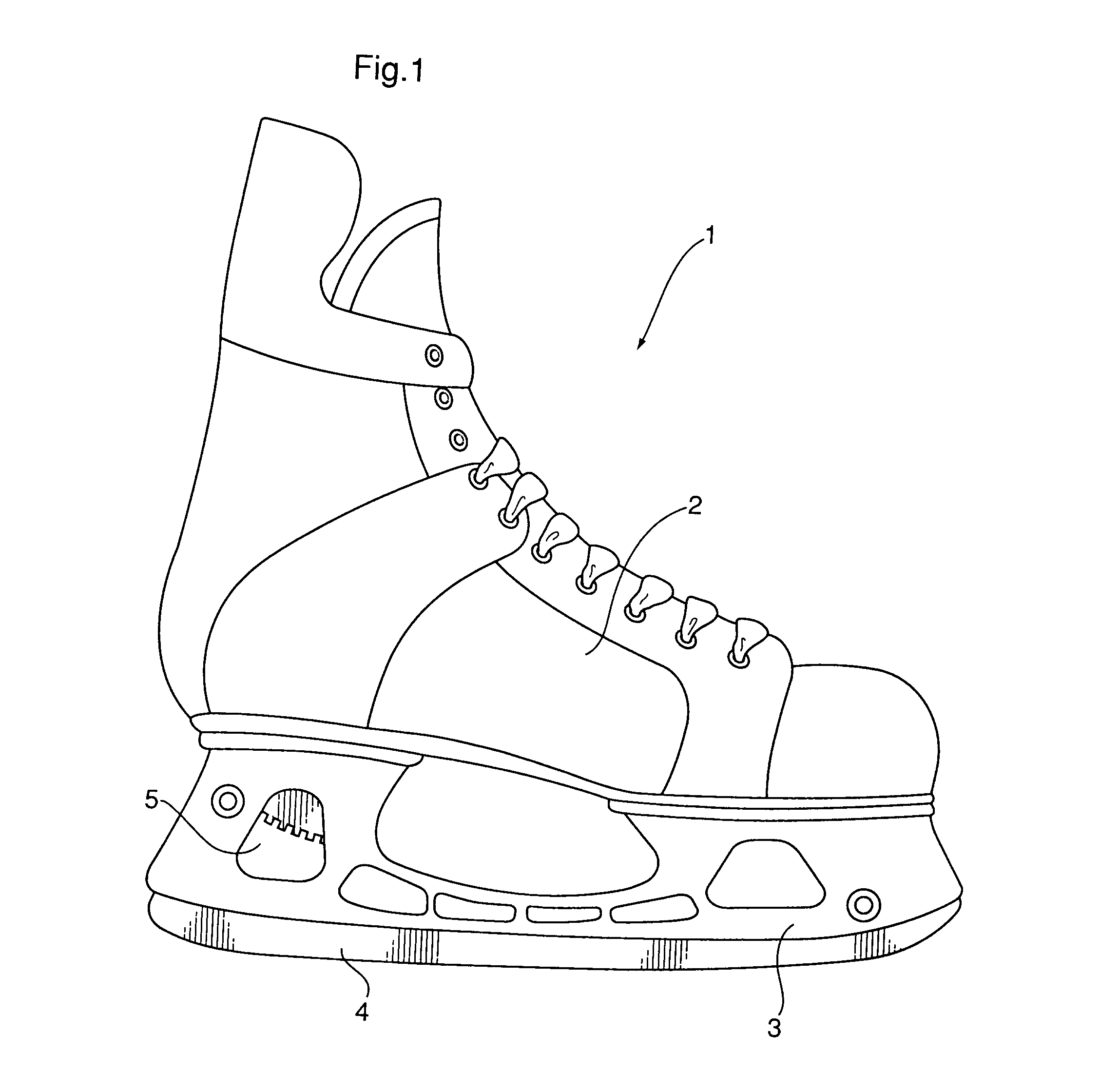
[0022]Referring to FIG. 1, a replaceable blade ice skate assembly (1) is substantially constructed from a boot (2), a holder (3) adapted to be mounted to the boot and a downward facing blade system (4). The holder (3) is styled to include at least one aesthetic aperture (5). It will be appreciated that this aperture could also have non-aesthetic functions, such as affecting the flexibility of the holder.

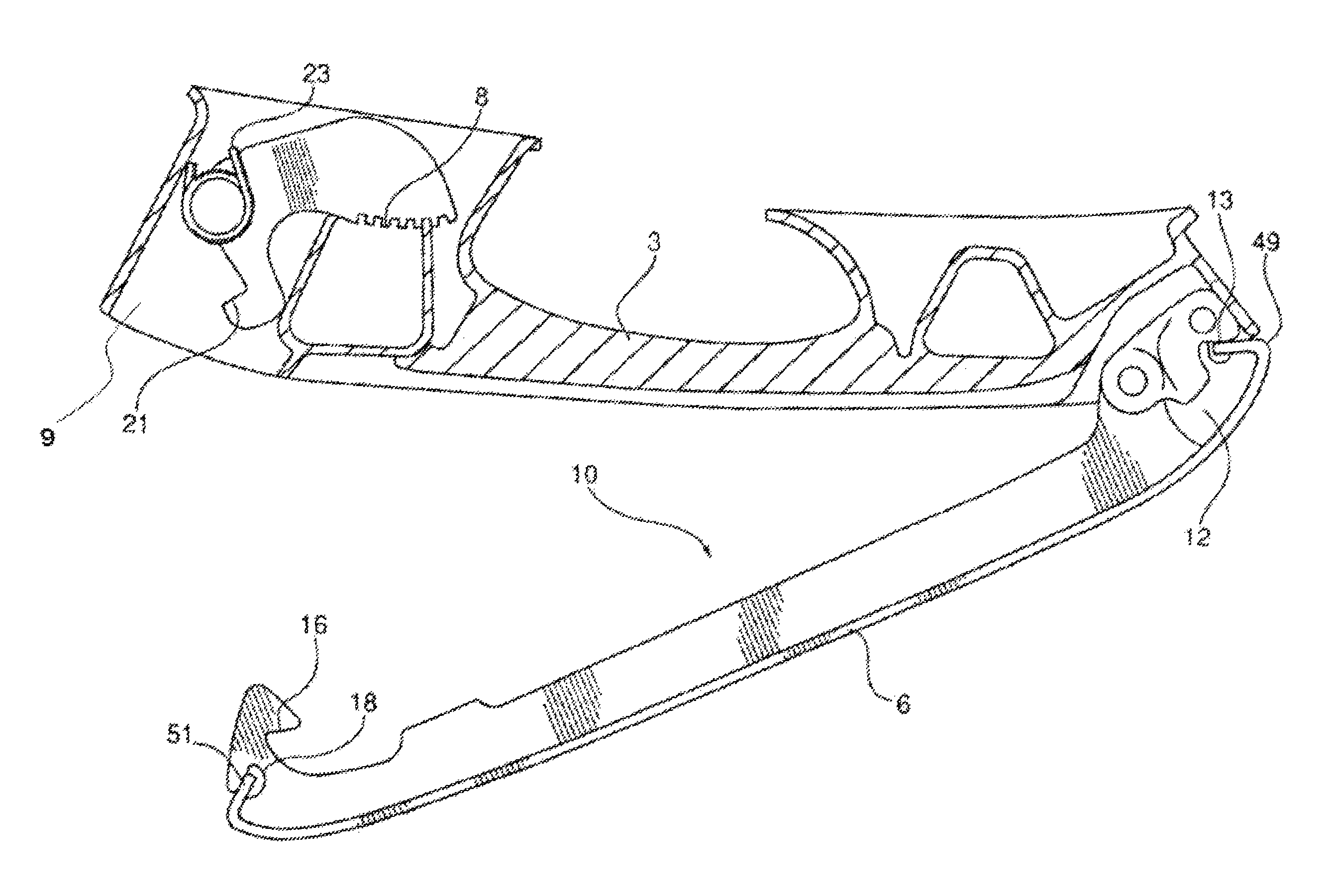
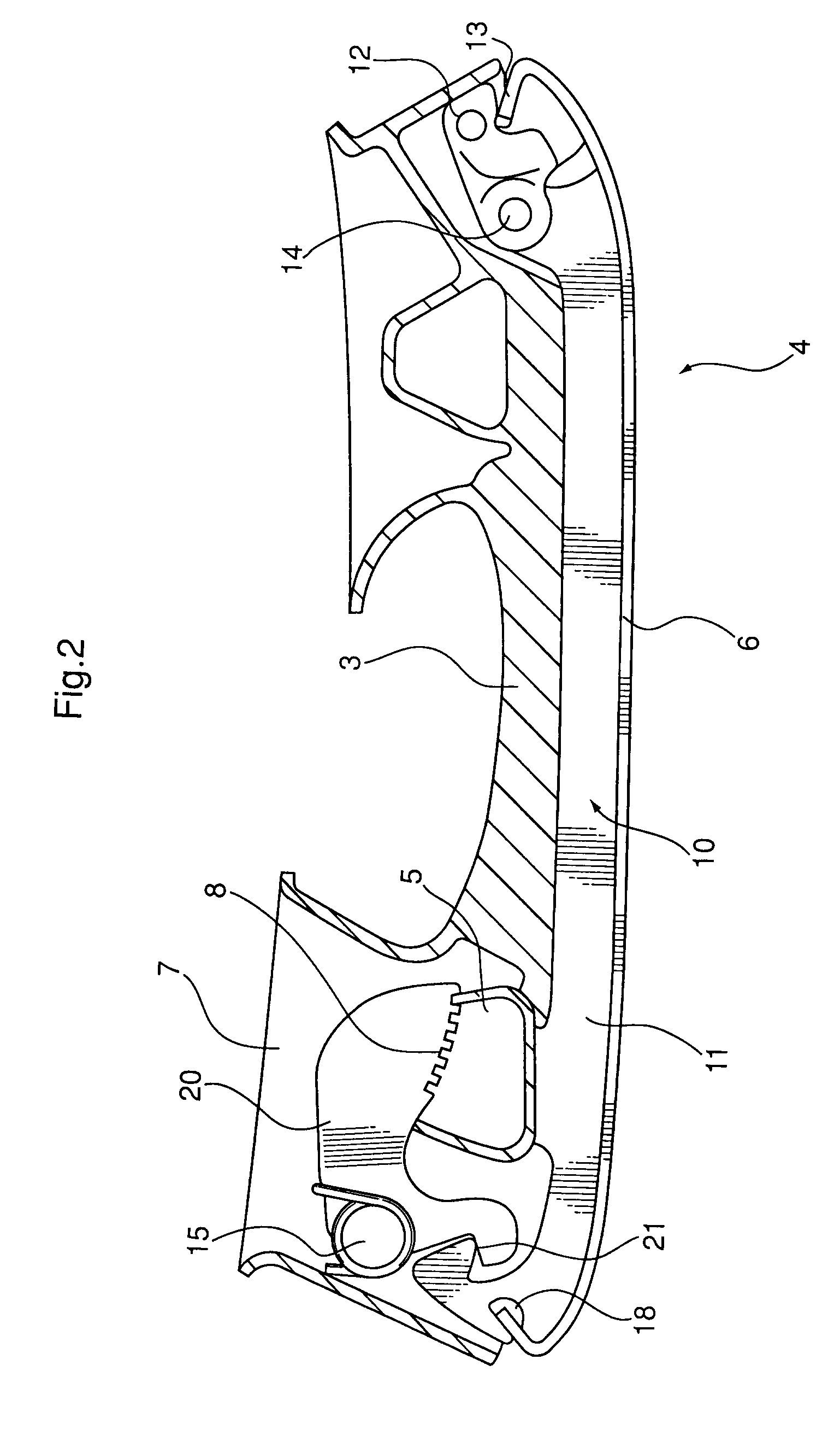
[0023]FIGS. 2 and 3 illustrate a flexible replaceable blade system that consists of a downward facing blade system (4) that includes a rocker (10) that is configured with a first defined curvature along its lower ice-contacting surface and incorporates a front end (12) and a rear end (11) and a flexible replaceable blade (6). The rocker front end (12) is adapted to be immovably attached to the holder (3) via riveting, bolting or similar fastening means and is configured with a toe receiving area (13). The rocker front end (12) is configured with a pivot joint (14) which is adapted to...


PUM


Abstract

A replaceable blade system for ice skates is provided with a rotary retention latch located within an enclosed chamber of the holder of the skate. The rotary retention latch is configured with a release lever that is adapted to be accessed through an aesthetic aperture in the holder.

Description

RELATED APPLICATIONS[0001]This application is a 35 U.S.C. 371 national stage filing from International Application No. PCT / CA2009 / 000338 filed Mar. 10, 2009, which claims priority to Canadian Patent Application No. 2,638,352, filed Jul. 25, 2008, the teachings of which are incorporated herein by reference.BACKGROUND[0002]Ice skates have been used for recreational and transportation purposes for hundreds of years. Originally, some sort of low friction sliding device akin to a metal blade was attached using straps to a conventional boot. Ultimately, in the past century, boots specifically intended for use only in ice skating evolved, typically with the blade firmly affixed to the boot. The unitary blade and boot had the advantage of rigidity allowing more speed and control than previously possible.[0003]For many years, it has been understood that there may be an advantage to providing a replaceable sharpened blade for ice skates. With heavy use, typically a conventional skate blade wi...

Claims


Application Information

Patent Timeline
Patent Type & Authority Patents(United States)
IPC IPC(8): A63C1/00
CPCA63C1/303
Inventor SALMON, JOHN JASPERHAMPTON, RICHARD CHARLES
Owner MULTIMATIC INC
Why Eureka
Try Eureka