Methods and apparatus for providing a sacrificial shield for a fuel injector

a fuel injector and sacrificial shield technology, which is applied in the direction of combustion types, lighting and heating apparatus, machines/engines, etc., can solve the problems of increasing the cost of gas turbine operation and typically limited life of fuel injectors, so as to reduce heat exposure, reduce heat exposure, and reduce heat exposure

Active Publication Date: 2013-10-15
AIR PROD & CHEM INC
View PDF11 Cites 14 Cited by
  • Summary
  • Abstract
  • Description
  • Claims
  • Application Information

AI Technical Summary

Benefits of technology

[0005]Embodiments of the invention can address some or all of the needs described above. According to one embodiment of the invention, there is disclosed a method for providing a sacrificial shield for a fuel injector. The method can include providing at least one shield support device operable to mount to a tip of a fuel injector. The method can also include mounting a plurality of shields to the at least one support device, wherein each of the plurality of shields is spaced apart from each respective adjacent shield by at least one segmentation, and wherein each of the plurality of shields is operable to reduce heat exposure to the tip of the fuel injector.
[0006]According to another embodiment of the invention, there is disclosed an apparatus for providing shielding to a fuel injector associated with a combustion device. The apparatus may include at least one shield support device operable to mount to a tip of a fuel injector. The apparatus can also include a plurality of shields to the at least one support device, wherein each of the plurality of shields is spaced apart from each respective adjacent shield by at least one segmentation, and wherein each of the plurality of shields is operable to reduce heat exposure to the tip of the fuel injector.
[0007]According to yet another embodiment of the invention, there is disclosed a fuel injector for a combustion system. The fuel injector can include a tip end. The fuel injector can also include at least one shield support device operable to mount to adjacent to the tip end. Furthermore, the fuel injector can include a plurality of shields to the at least one support device, wherein each of the plurality of shields is spaced apart from each respective adjacent shield by at least one segmentation, and wherein each of the plurality of shields is operable to reduce heat exposure to the tip of the fuel injector.

Problems solved by technology

Fuel injectors typically have a limited life span due to their constant exposure to high temperatures.
However, conventional fuel injectors using water cooling require operating and maintaining associated water circulation systems, which increase the cost to operate the gas turbine.

Method used


Image

  • Methods and apparatus for providing a sacrificial shield for a fuel injector
  • Methods and apparatus for providing a sacrificial shield for a fuel injector
  • Methods and apparatus for providing a sacrificial shield for a fuel injector

Examples


Embodiment Construction

[0020]Illustrative embodiments of the invention now will be described more fully hereinafter with reference to the accompanying drawings. Indeed, the invention may be embodied in many different forms and should not be construed as limited to the embodiments set forth herein; rather, these embodiments are provided so that this disclosure will satisfy applicable legal requirements. Like numbers refer to like elements throughout.

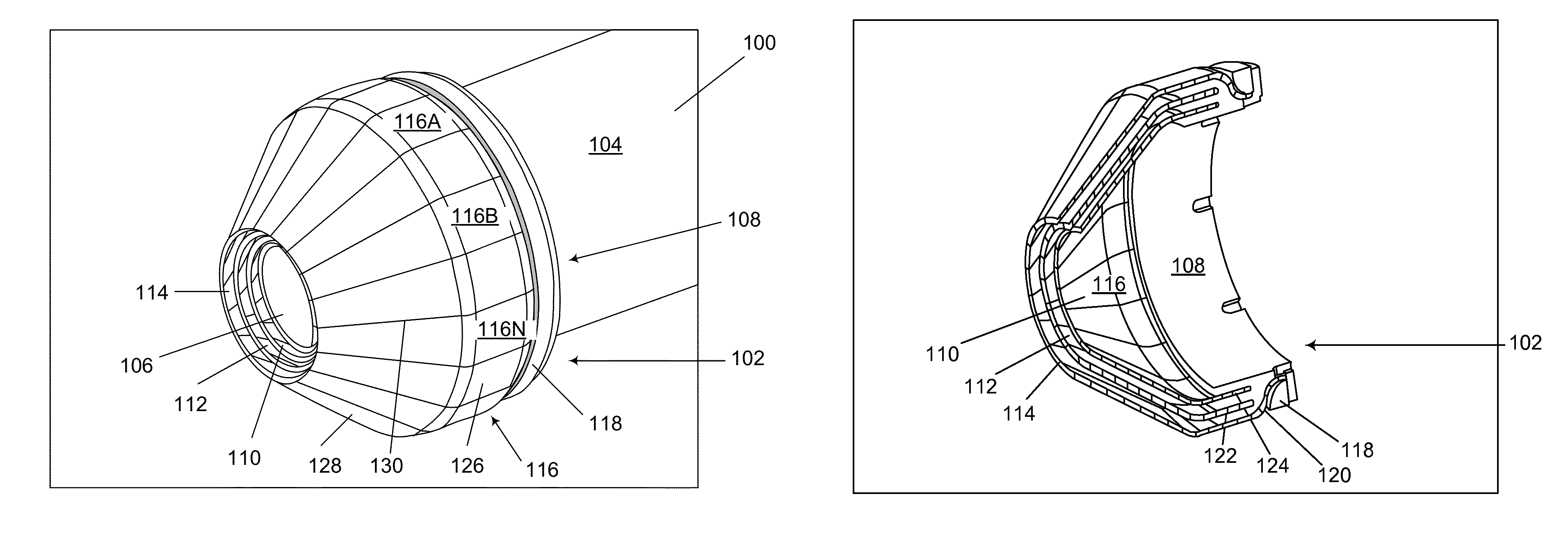
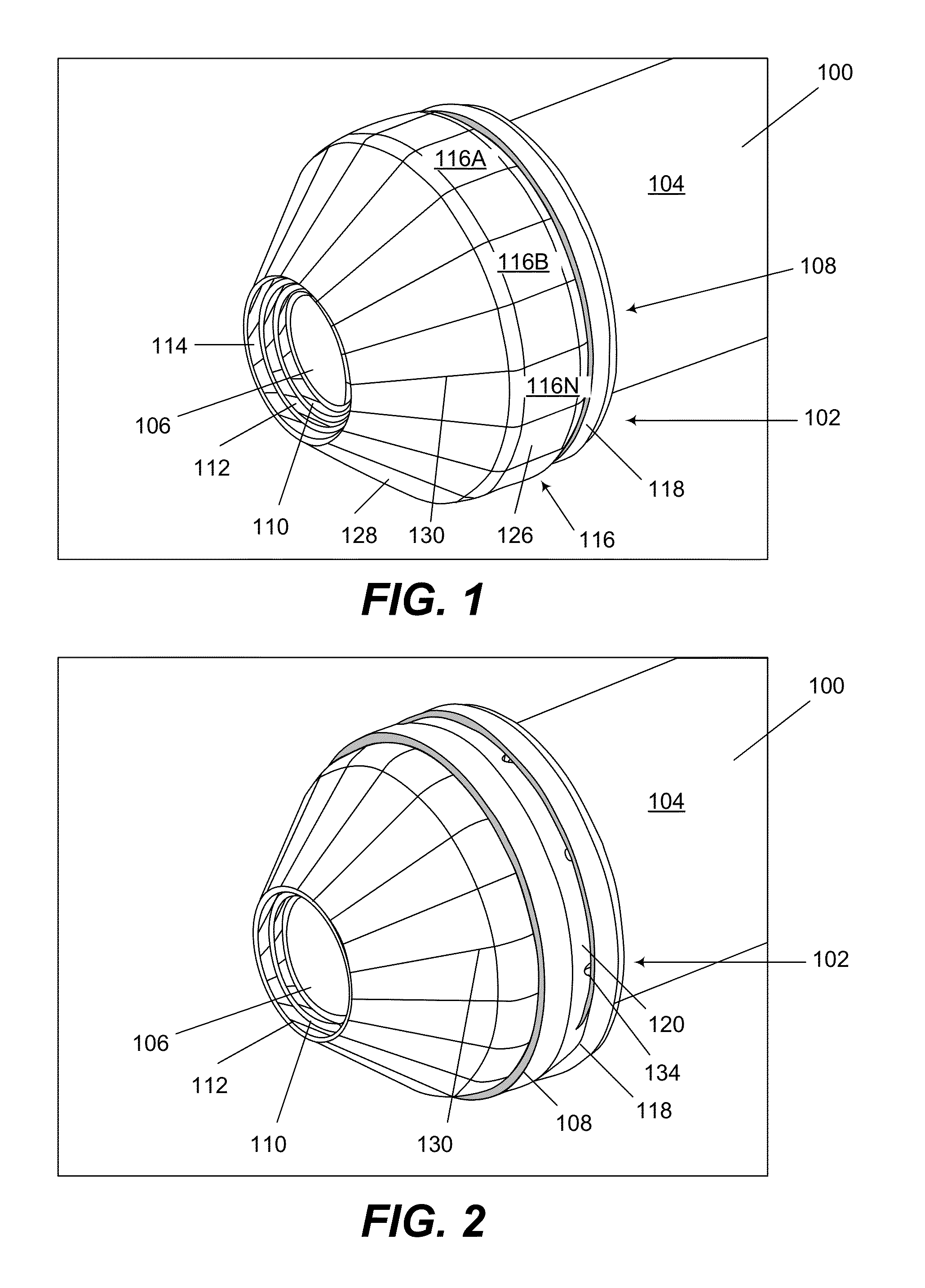
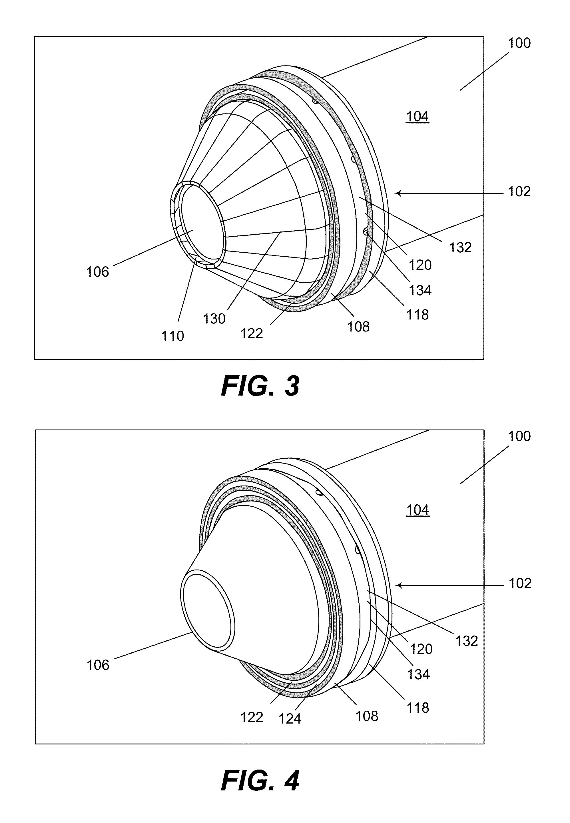
[0021]Disclosed are methods and methods and apparatus for providing a sacrificial shield for a fuel injector. FIG. 1 illustrates a perspective view of an example fuel injector 100 and apparatus 102 in accordance with an embodiment of the invention. FIGS. 2-9 illustrate various views of either or both the example fuel injector 100 and apparatus 102 shown in FIG. 1. FIG. 1 shows certain components of an example fuel injector 100, which includes a body 104 and a tip 106 adjacent to one end of the body 104. In the embodiment shown in FIGS. 1-4 and 7, the body 104 c...


PUM


Abstract

Embodiments of methods and apparatus for providing a sacrificial shield for a fuel injector are provided. According to one example embodiment, a method for shielding a fuel injector associated with a combustion device is provided. The method can include providing at least one shield support device operable to mount to a tip of a fuel injector. The method can also include mounting a plurality of shields to the at least one support device, wherein each of the plurality of shields is spaced apart from each respective adjacent shield by at least one segmentation, and wherein each of the plurality of shields is operable to reduce heat exposure to the tip of the fuel injector.

Description

FIELD OF THE INVENTION[0001]The invention relates to combustion equipment, and more specifically relates to methods and apparatus for providing a sacrificial shield for a fuel injector.BACKGROUND OF THE INVENTION[0002]Generally, fuel is introduced into a combustion chamber for a gas turbine by one or more fuel injectors. Various fuels can include natural gas, coal slurry, and other fossil fuel-based, carbon-based or hydrogen-based fuels. Fuel injectors typically have a limited life span due to their constant exposure to high temperatures. High temperatures are caused by radiant heat from the partial combustion of fuel and oxygen within the combustion chamber. When a fuel injector begins to show heat damage or otherwise fails due to overheating, the associated gas turbine must be shut down to permit repairs or replacement of the damaged fuel injector.[0003]At least one conventional fuel injector uses water circulation to cool particular portions of the fuel injector. In such a fuel i...

Claims


Application Information

Patent Timeline
Patent Type & Authority Patents(United States)
IPC IPC(8): F23R3/60
CPCF02C7/22F02C7/24F23D11/38F23D14/76F23D2212/10F23D2212/20
Inventor DIMASCIO, PAUL STEPHENHARNED, MONTY LEE
Owner AIR PROD & CHEM INC
Why Eureka
Try Eureka