Covnenient plug type 3D printing spray head

A 3D printing, plug-in technology, applied in the field of 3D printing nozzles, can solve the problems of circuit connection components occupying a large space, expansion tube blockage, easy damage, etc., to save socket space, good lubricity, and low heat. Effect

Inactive Publication Date: 2014-09-03
句容利威尔电器有限公司
View PDF4 Cites 3 Cited by
  • Summary
  • Abstract
  • Description
  • Claims
  • Application Information

AI Technical Summary

Problems solved by technology

[0005] Purpose of the invention: In order to overcome the deficiencies in the prior art, the present invention provides a convenient plug-in 3D printing nozzle, which solves the problem of clogging of the internal expansion tube in the through hole before the consumables are introduced into the nozzle, and further solves the problem of the 3D printing nozzle. During the plugging process, the circuit connection device occupies a large space, is unstable, and is easily damaged

Method used


Image

  • Covnenient plug type 3D printing spray head
  • Covnenient plug type 3D printing spray head

Examples


Embodiment 1

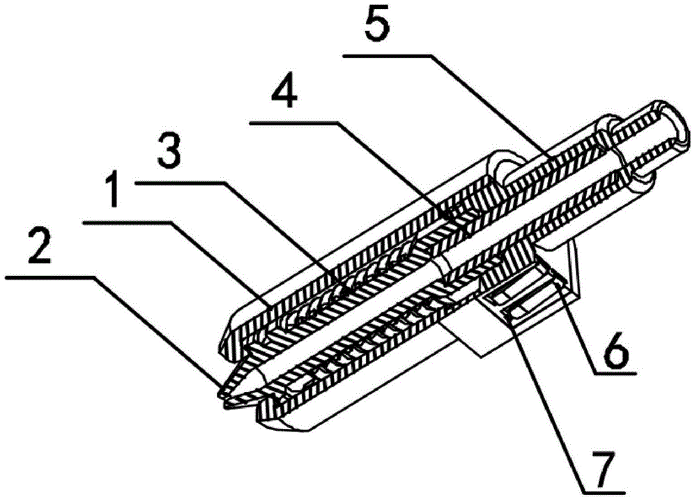
[0014] Embodiment 1: the structural representation of the present invention is as figure 1 As shown, it includes a housing 1 , a nozzle 2 , a heating device 3 surrounding the outer wall of the nozzle 2 , a plastic introduction pipe 4 , a fixing seat 5 and a metal terminal 6 .

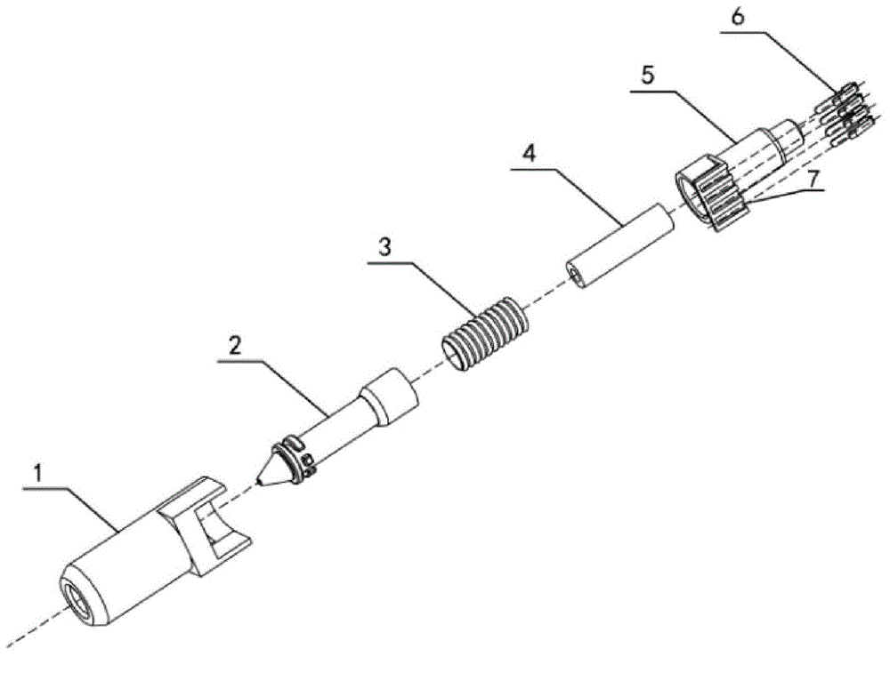
[0015] The assembly diagram of the present invention is as follows figure 2 As shown, the fixing seat 5 is provided with a through hole and is fixedly arranged in the cavity of the housing 1, the plastic introduction tube 4 is sleeved in the through hole of the fixing seat 5, and is connected with the through hole of the nozzle 2 to form a consumable The conveying cavity; the fixed seat 5 is provided with a terminal card slot 7, and the metal terminal 6 is fixedly arranged on the terminal card slot 7; the power line of the heating device 3 is connected to the metal terminal 6, and the metal terminal 6. SMD connection with the control circuit of the 3D printing device. In this embodiment, it is directl...

Embodiment 2

[0017] Embodiment 2: the structural representation of the present invention is as figure 1 As shown, it includes a housing 1, a nozzle 2, a heating device 3 surrounding the outer wall of the nozzle 2, a plastic introduction pipe 4, a fixing seat 5 and a metal terminal 6, and a temperature sensor is also provided in the cavity of the housing 3.

[0018] The assembly diagram of the present invention is as follows figure 2 As shown, the fixing seat 5 is provided with a through hole and is fixedly arranged in the cavity of the housing 1, the plastic introduction tube 4 is sleeved in the through hole of the fixing seat 5, and is connected with the through hole of the nozzle 2 to form a consumable Conveying cavity; the fixed seat 5 is provided with a terminal card slot 7, and the metal terminal 6 is fixedly arranged on the terminal card slot 7; the power line of the heating device 3 and the signal line of the temperature sensor are connected to the metal terminal 6 Above, the meta...


PUM


Abstract

The invention discloses a convenient plug type 3D printing spray head. The spray head comprises a shell, a nozzle, a heating device surrounding the outer wall of the nozzle, a fixed seat, a plastic introducing pipe and a metal terminal, wherein the fixed seat is provided with a through hole and is fixedly arranged in a cavity of the shell, and the plastic introducing pipe is arranged in the through hole of the fixed seat in a sleeving manner and is abutted with a through hole of the nozzle to form a consumable conveying cavity; a terminal clamping trough is formed in the fixed seat, and the metal terminal is fixedly arranged on the terminal clamping trough; a power supply wire of the heating device is connected to the metal terminal, and the metal terminal is in patch connection with a control circuit of 3D printing equipment; the melting point of the plastic introducing pipe is higher than that of a consumable. According to the convenient plug type 3D printing spray head, the problem that the consumable expands to block the pipe before being introduced into the through hole of the nozzle is solved; meanwhile, the metal terminal connected with the heating device is arranged in the clamping trough of the fixed seat, and the metal terminal is directly in the patch connection with a PCB (printed circuit board) of the control circuit of the printing equipment, so that the problems that a circuit connecting device is large in occupying space, is unstable and is easy to damage in inserting-plugging processes of the spray head are solved.

Description

technical field [0001] The invention relates to a 3D printing component, in particular to a 3D printing nozzle. Background technique [0002] In the past, 3D printing nozzles were integrated on 3D printers and drawing pens and could not be replaced, which limited the scope of use of 3D printing equipment. During the three-dimensional creation process of existing 3D printers and drawing pens, consumables of various colors and materials may be used according to the printing model set by the user. , the nozzles of 3D printers and drawing pens need to be replaced frequently to meet different requirements. [0003] Improvements have been made to address this problem in the industry. On the one hand, the detachable connection between the 3D printing nozzle and the printing equipment is realized in the mechanical structure. Separation is currently achieved by setting a pin-type power connector on the nozzle holder to connect with the control circuit on the 3D printing device, thu...

Claims


Application Information

Patent Timeline
Patent Type & Authority Applications(China)
IPC IPC(8): B29C67/00
Inventor 魏宏辉魏天浩魏妗羽
Owner 句容利威尔电器有限公司
Why Eureka
Try Eureka