High-pressure cleaning appliance with movable channel constriction section

a cleaning appliance and movable channel technology, applied in the direction of cleaning processes and utensils, cleaning using liquids, chemistry apparatus and processes, etc., can solve the problems of not being able to use high-pressure cleaning appliances, and achieve the effect of convenient setting member handling, low space requirement, and simple construction design

Active Publication Date: 2013-10-15
ALFRED KARCHER GMBH & CO KG
View PDF11 Cites 3 Cited by
  • Summary
  • Abstract
  • Description
  • Claims
  • Application Information

AI Technical Summary

Benefits of technology

[0008]A sliding displacement of the channel constriction section relative to the flow channel in the high-pressure cleaning appliance in accordance with the invention can effect a change in the free cross-sectional area of the flow channel, which is linearly dependent upon the path of displacement of the channel constriction section relative to the flow channel. This is not possible with high-pressure cleaning appliances with a channel constriction section rotatable relative to the flow channel that are known from the prior art. There the change in the free cross-sectional area occurs in dependence upon the change in the angle between the channel constriction section and the flow channel. In particular, the change in the free cross-sectional area does not depend linearly on the change in the angle. Owing to the linear dependence of the change in the free cross-sectional area on the path of displacement of the channel constriction section in the high-pressure cleaning appliance in accordance with the invention, the change in the amount and, therefore, also the total amount of combustion air supplied to the heat exchanger can, in practice, be set more precisely.
[0042]It is advantageous for the channel constriction section to pass through a through-opening formed in a wall of the flow channel. This makes it possible for the channel constriction section to engage in the flow channel so that when the channel constriction section is displaced relative to the flow channel, its free cross-sectional area can be changed.

Problems solved by technology

This is not possible with high-pressure cleaning appliances with a channel constriction section rotatable relative to the flow channel that are known from the prior art.

Method used


Image

  • High-pressure cleaning appliance with movable channel constriction section
  • High-pressure cleaning appliance with movable channel constriction section
  • High-pressure cleaning appliance with movable channel constriction section

Examples


Embodiment Construction

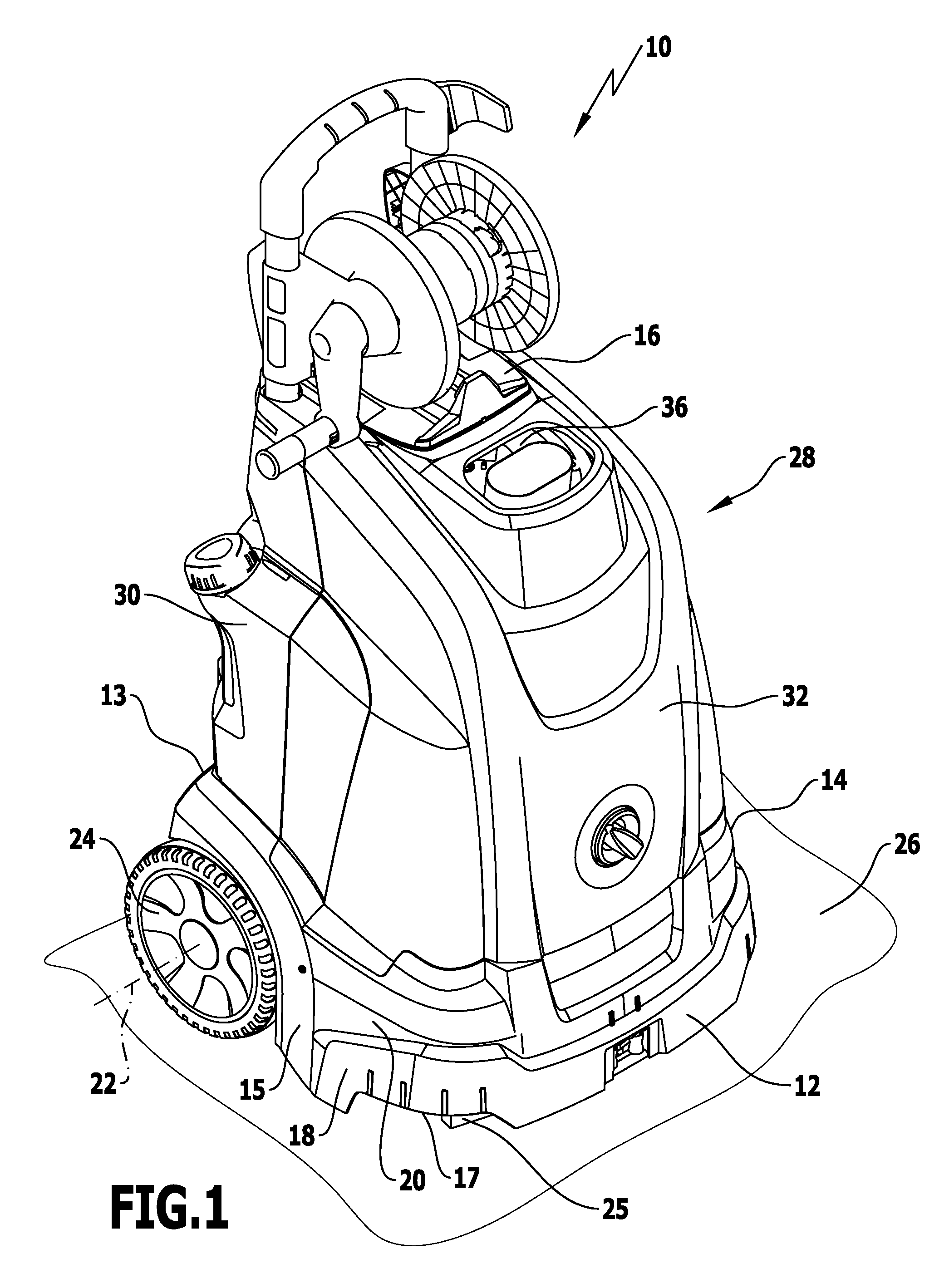
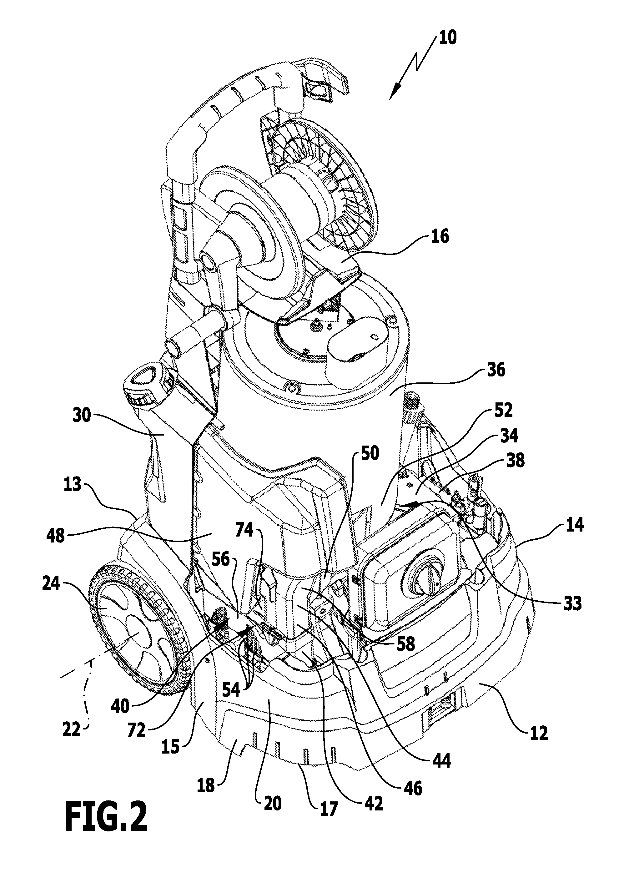
[0050]A preferred embodiment of a high-pressure cleaning appliance in accordance with the invention is shown in perspective in FIG. 1 and designated in its entirety by reference numeral 10 therein. It comprises a front side 12, a rear side 13, a left side 14, a right side 15, an upper side 16 and an underside 17.

[0051]The high-pressure cleaning appliance 10 comprises a bottom part 18 with a chassis 20 on which two wheels rotatable about a common axis of rotation 22 are held near the rear side 13. Only one wheel 24 of these is shown in the drawings. The high-pressure cleaning appliance 10 can stand on a set-down surface 26 with the wheel 24 and the wheel that is not shown and with a plurality of support elements formed on the underside 17 of the chassis 20, only one support foot 25 of which is shown.

[0052]The high-pressure cleaning appliance 10 comprises a housing 28 above the bottom part 18. The housing 28 comprises a housing wall 30 in the area of the rear side 13 and of the sectio...


PUM


Abstract

The invention relates to a high-pressure cleaning appliance, comprising a heatable heat exchanger for heating up a liquid dispensable by the high-pressure cleaning appliance, a blower with a flow channel connected thereto for supplying combustion air to the heat exchanger, and a setting member for setting the amount of combustion air suppliable to the heat exchanger, the setting member having a channel constriction section which is positionable in the flow channel and movable relative thereto for changing the free cross-sectional area of the flow channel. In order to develop a generic high-pressure cleaning appliance further so that the amount of combustion air suppliable to the heat exchanger can be better adjusted, it is proposed that the channel constriction section be configured so as to be slidingly displaceable relative to the flow channel.

Description

[0001]This application is a continuation of international application number PCT / EP2010 / 061378 filed on Aug. 5, 2010 and claims the benefit of German application number 20 2009 014 093.8 filed on Oct. 14, 2009.[0002]The present disclosure relates to the subject matter disclosed in international application number PCT / EP2010 / 061378 of Aug. 5, 2010 and German application number 20 2009 014 093.8 of Oct. 14, 2009, which are incorporated herein by reference in their entirety and for all purposes.BACKGROUND OF THE INVENTION[0003]The invention relates to a high-pressure cleaning appliance, comprising a heatable heat exchanger for heating up a liquid dispensable by the high-pressure cleaning appliance, a blower with a flow channel connected thereto for supplying combustion air to the heat exchanger, and a setting member for setting the amount of combustion air suppliable to the heat exchanger, the setting member having a channel constriction section which is positionable in the flow channe...

Claims


Application Information

Patent Timeline
Patent Type & Authority Patents(United States)
IPC IPC(8): B08B3/00
CPCB08B3/00B08B2203/007
Inventor BOEHM, MICHAELPFAFF, PETERSCHWAB, WERNER
Owner ALFRED KARCHER GMBH & CO KG
Why Eureka
Try Eureka