Optical fiber type vibration meter

Inactive Publication Date: 2011-07-14
MITUTOYO CORP
View PDF9 Cites 0 Cited by
  • Summary
  • Abstract
  • Description
  • Claims
  • Application Information

AI Technical Summary

Benefits of technology

[0012]One aspect of the present invention is an optical fiber type vibration meter having a light source; an optical fiber guiding light from the light source; a vibration probe to which the guided light is made incident; an optical receiver photoelectric-converting light modulated by a vibration of a movable member arranged in the vibration probe to output the light as an electrical signal; a processor processing the electrical signal to output a state of the vibration as an output voltage value; a velocity pickup converting a velocity of the movable member arising from the vibration of the movable member into an electrical current; a solenoidal coil generating a magnetic field by the electrical current; and a magnetic field sensor attenuating an amount of light guided to the vibration probe according to an intensity of the magnetic field.
[0013]According to another aspect of the present invention, the magnetic field sensor changes an amount of light guided to the vibration probe also according to a direction of a magnetic field generated by the solenoidal coil.
[0014]According to an

Problems solved by technology

Therefore, when a cable from the vibration probe is long, it is susceptible to electromagnetic induction noises.
At the same time, transmission loss via a cable cannot be ignored, and it is possible that signal quality may deteriorate.
Therefore, in Related Art 1, the acceleration output is affected by static gravity, and an offset error occurs.
However, for the former two, when it is an asy

Method used


Image

  • Optical fiber type vibration meter
  • Optical fiber type vibration meter
  • Optical fiber type vibration meter

Examples


first embodiment

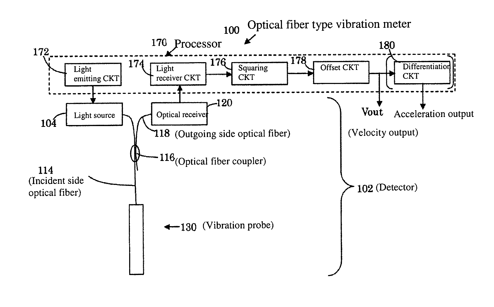
[0039]First, an overview of an optical fiber type vibration meter is explained using FIG. 1 and FIG. 2.

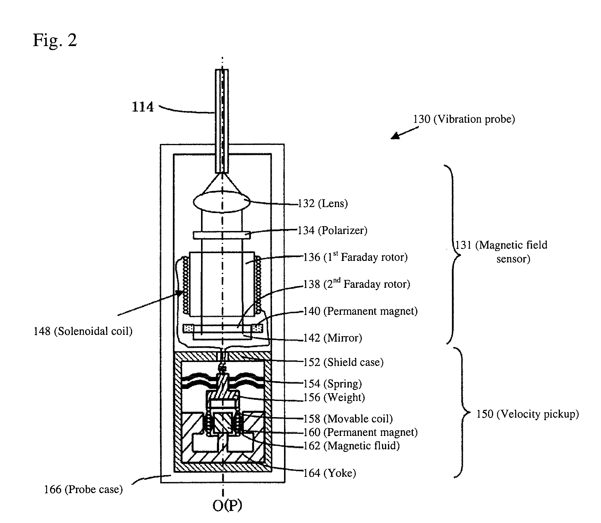
[0040]As illustrated in FIG. 1 and FIG. 2, an optical fiber type vibration meter 100 has a light source 104; an incident side optical fiber 114 (optical fiber) guiding light from the light source 104; a vibration probe 130 to which the guided light is made incident; an optical receiver 120 photoelectric-converting light modulated by vibration of a weight 156 and a movable coil 158 (movable member) arranged in the vibration probe 130 to output the light as an electrical signal; and a processor 170 processing the electrical signal to output a state (velocity) of the vibration as an output voltage value Vout.

[0041]As illustrated in FIG. 2, the optical fiber type vibration meter 100 includes a velocity pickup 150 converting a velocity of the weight 156 and the movable coil 158 arising from the vibration of the weight 156 and the movable coil 158 into an electrical current (which is pr...

second embodiment

[0087]Further, in the present embodiment, the weight 156 is supported by the circular plate shaped spring 154, the permanent magnet 160 of the velocity pickup 150 is arranged in a shape following the inner periphery of the movable coil 158, and the yoke 164 is arranged in a ring shape on the outside of the movable coil 158. However, the present invention is not limited to this. For example, as in a velocity pickup 250 according to the present invention as illustrated in FIG. 7, it is also possible to use a plate spring 254 to cantilever a movable coil 258, which is integrally configured with a weight. And, it is also possible to fix two square permanent magnets 260 on outer portions of a yoke 264 in such a way that the permanent magnets 260 face a portion of the yoke 264 inside the movable coil 258. Of course, it is also possible to arrange permanent magnets both inside and outside a movable coil. In that case, it is not limited to a bi-directional arrangement. And, a magnetic pole ...

third embodiment

[0089]Next, the present invention is explained using FIG. 8 and FIG. 9.

[0090]In the present embodiment, the reflection type vibration probe 130 of the first embodiment is made multiaxial. A schematic configuration of this is as illustrated in FIG. 8 and FIG. 9. Light of a plurality of wavelengths λ1-λ3 from a light source 304 is guided to an incident side optical fiber (optical fiber) 314. At a vibration probe 330, light outgoing from the incident side optical fiber 314 is dispersed into each of the wavelengths λ1-λ3, and is modulated (attenuated) by vibrations detected at the same number of velocity pickups 350X-350Z as the wavelengths. In this case, the light outgoing from the incident side optical fiber 314 is dispersed into each of the wavelengths by two dichroic mirrors 333Y and 333Z. Specific configuration is explained in the following. Other than related to a part involving multiaxial, explanation is omitted as appropriate.

[0091]As illustrated in FIG. 8, the light source 304,...


PUM


Abstract

An optical fiber type vibration meter including a light source, an incident side optical fiber guiding light from the light source, a vibration probe to which a guided light is made incident, an optical receiver photoelectric-converting light modulated by a vibration of a weight and a movable coil arranged in the vibration probe to output the light as an electrical signal, a processor processing the electrical signal to output a state of the vibration as an output voltage value, a velocity pickup converting a velocity of the weight and the movable coil arising from the vibration of the weight and the movable coil into an electrical current, a solenoidal coil generating a magnetic field by the electrical current, and a magnetic field sensor attenuating an amount of light guided to the vibration probe according to an intensity of the magnetic field.

Description

CROSS-REFERENCE TO RELATED APPLICATIONS[0001]The present application claims priority under 35 U.S.C. §119 of Japanese Application No. 2010-003237, filed on Jan. 8, 2010, the disclosure of which is expressly incorporated by reference herein in its entirety.BACKGROUND OF THE INVENTION[0002]1. Field of the Invention[0003]The present invention relates to an optical fiber type vibration meter having a light source; an optical fiber guiding light from the light source, a vibration probe to which the guided light is made incident; an optical receiver photoelectric-converting light modulated by vibration of a movable member arranged in the vibration probe to output the light as an electrical signal; and a processor processing the electrical signal to output a state of the vibration as an output voltage value. In particular, the present invention relates to an optical fiber type vibration meter capable of high precision measurement.[0004]2. Description of Related Art[0005]Conventionally, the...

Claims


Application Information

Patent Timeline
IPC IPC(8): G01H9/00
CPCG01H9/004
Inventor MIKI, YUTAKA
Owner MITUTOYO CORP
Why Eureka
Try Eureka