X-ray imaging apparatus

a technology of x-ray imaging and x-ray, applied in the direction of radiation generation arrangements, medical science, diagnostics, etc., can solve problems such as complicated operation, and achieve the effect of simple operation and changeable amount of assist from a driv

Active Publication Date: 2020-07-02
SHIMADZU CORP
View PDF0 Cites 0 Cited by
  • Summary
  • Abstract
  • Description
  • Claims
  • Application Information

AI Technical Summary

Benefits of technology

[0006]The present invention is intended to solve the above problem. The present invention aims to provide an X-ray imaging apparatus in which the amount of assist from a drive can be changed by a simple operation when a moving body configured to movably support at least one of an X-ray irradiator and an X-ray detector is manually moved.

Problems solved by technology

Therefore, the operation becomes complicated when the amount of assist from the motor is changed.

Method used


Image

  • X-ray imaging apparatus
  • X-ray imaging apparatus
  • X-ray imaging apparatus

Examples


modified examples

[0067]The embodiment disclosed this time must be considered as illustrative in all points and not restrictive. The scope of the present invention is not shown by the above description of the embodiment but by the scope of claims for patent, and all modifications (modified examples) within the meaning and scope equivalent to the scope of claims for patent are further included.

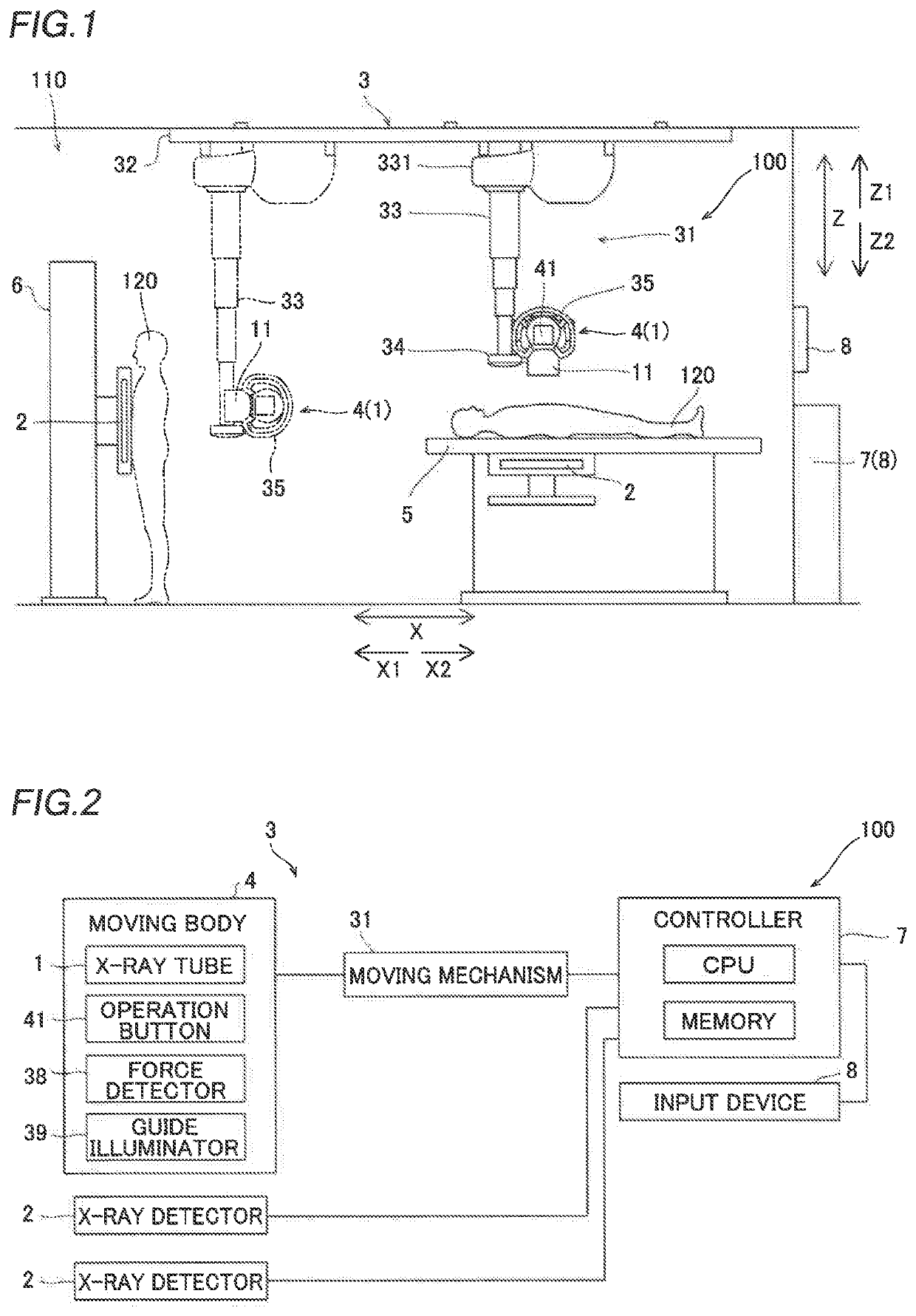
[0068]For example, while the ceiling-suspended X-ray imaging apparatus (ceiling-suspended holding mechanism) is shown as an example in the aforementioned embodiment, the present invention is not limited to this. The present invention may alternatively be applied to a structure other than the ceiling-suspended structure. For example, the present invention may be applied to a floor traveling X-ray imaging apparatus. Alternatively, the present invention may be applied to a C-arm type X-ray imaging apparatus, or the present invention may be applied to a proximate fluoroscopic table. Alternatively, the present invent...


PUM


Abstract

An X-ray imaging apparatus includes a controller configured or programmed to perform control to change an amount of assist from a drive in manually moving a moving body based on at least one of operation of an operation button configured to receive an operation for moving the moving body or an operation for aligning the moving body and a current position and target position of the moving body.

Description

CROSS-REFERENCE TO RELATED APPLICATIONS[0001]This application claims the benefit of priority to Japanese Patent Application No. 2018-242091 filed on Dec. 26, 2018. The entire contents of this application are hereby incorporated herein by reference.BACKGROUND OF THE INVENTIONField of the Invention[0002]The present invention relates to an X-ray imaging apparatus.Description of the Background Art[0003]Conventionally, an X-ray imaging apparatus is known. Such an X-ray imaging apparatus is disclosed in Japanese Patent Laid-Open No. 2010-227376, for example.[0004]Japanese Patent Laid-Open No. 2010-227376 discloses a radiographic imaging apparatus (X-ray imaging apparatus) including a radiation source that irradiates a subject with X-rays, radiation detection means that detects the X-rays transmitted through the subject, a motor that moves the radiation source, and a control unit that assists in moving the radiation source by driving the motor when the radiation source is manually moved. I...

Claims


Application Information

Patent Timeline
Patent Type & Authority Applications(United States)
IPC IPC(8): A61B6/00A61B6/08
CPCA61B6/4452A61B6/08A61B6/54A61B6/4482A61B6/40A61B6/44A61B6/0487A61B6/4464A61B6/4476A61B6/588A61B6/587
Inventor SHIROTA, KENSAKAGUCHI, JUNPEIOKUMURA, HIROSHI
Owner SHIMADZU CORP
Why Eureka
Try Eureka