Diaphragm sheet transfer device

Active Publication Date: 2021-08-31
TDK TAIWAN
View PDF8 Cites 0 Cited by
  • Summary
  • Abstract
  • Description
  • Claims
  • Application Information

AI Technical Summary

Benefits of technology

This patent is about a device that can change the amount of light that enters a camera or recording lens on a handheld electronic device. This is done by using a movable diaphragm sheet with two light through holes that can be transferred to the incident light path by changing the position of the diaphragm sheet. The two light through holes have different opening areas, and by driving the diaphragm sheet to different positions, the amount of light incident can be adjusted. The device can also have multiple movable diaphragm sheets with independent hollow portions that can be driven to change the extent of the hollow portions between the sheets. This allows for more creative control over the light path and the amount of light incident on the lens.

Problems solved by technology

However, the diaphragm of the mobile phone is a fixed diaphragm, and it cannot be zoomed in or zoomed out as a normal camera lens.
However, since the volume of the mobile phone is required to be thin and lightweight, it is not obviously suitable for the diaphragm motor to be configured in the mobile phone.
However, this is contrary to the design of the thin and lightweight requirement of smart phones.
In addition to the large space occupied by the diaphragm motor and the relatively large power consumption required, another limiting factor is the diaphragm structure of the lens.
Since the lens is easily scratched, the adjustment of the diaphragm cannot be implemented in the smart phone.

Method used


Image

  • Diaphragm sheet transfer device
  • Diaphragm sheet transfer device
  • Diaphragm sheet transfer device

Examples


first embodiment

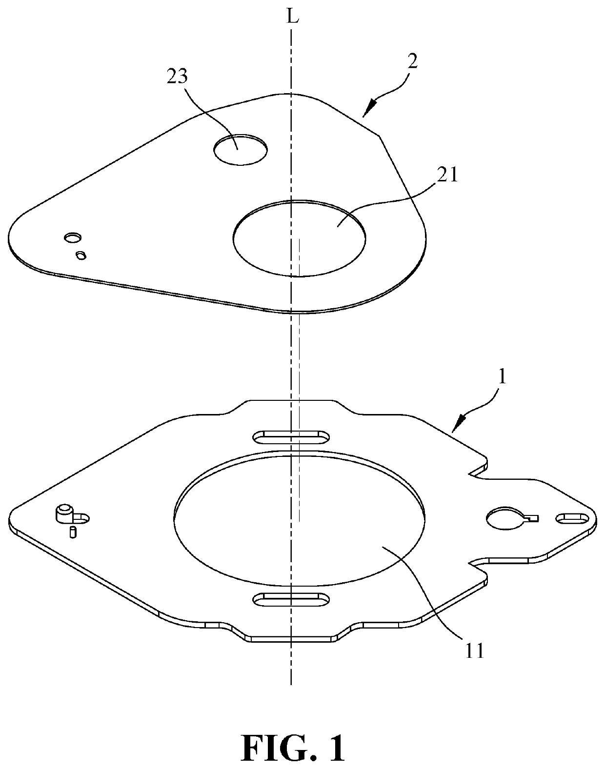
[0025]The movable plate 1 has a first opening 11 through which the incident light passes, and the movable diaphragm sheet 2 has two light through holes 21 and 23 having different opening areas. The two light through holes in the first embodiment are independent of each other and are not staggered with each other.

[0026]When the movable plate 1 is at an initial position, only the large (small) light through hole 21 of the movable diaphragm sheet 2 corresponds to the first opening hole 11, and when the movable plate 1 is at a transfer position, only the small (large) light through hole 23 of the movable diaphragm sheet 2 corresponds to the first opening 11.

[0027]The specific connection relationship and action relationship between the movable plate 1 and the movable diaphragm sheet 2 are further explained in the following embodiments.

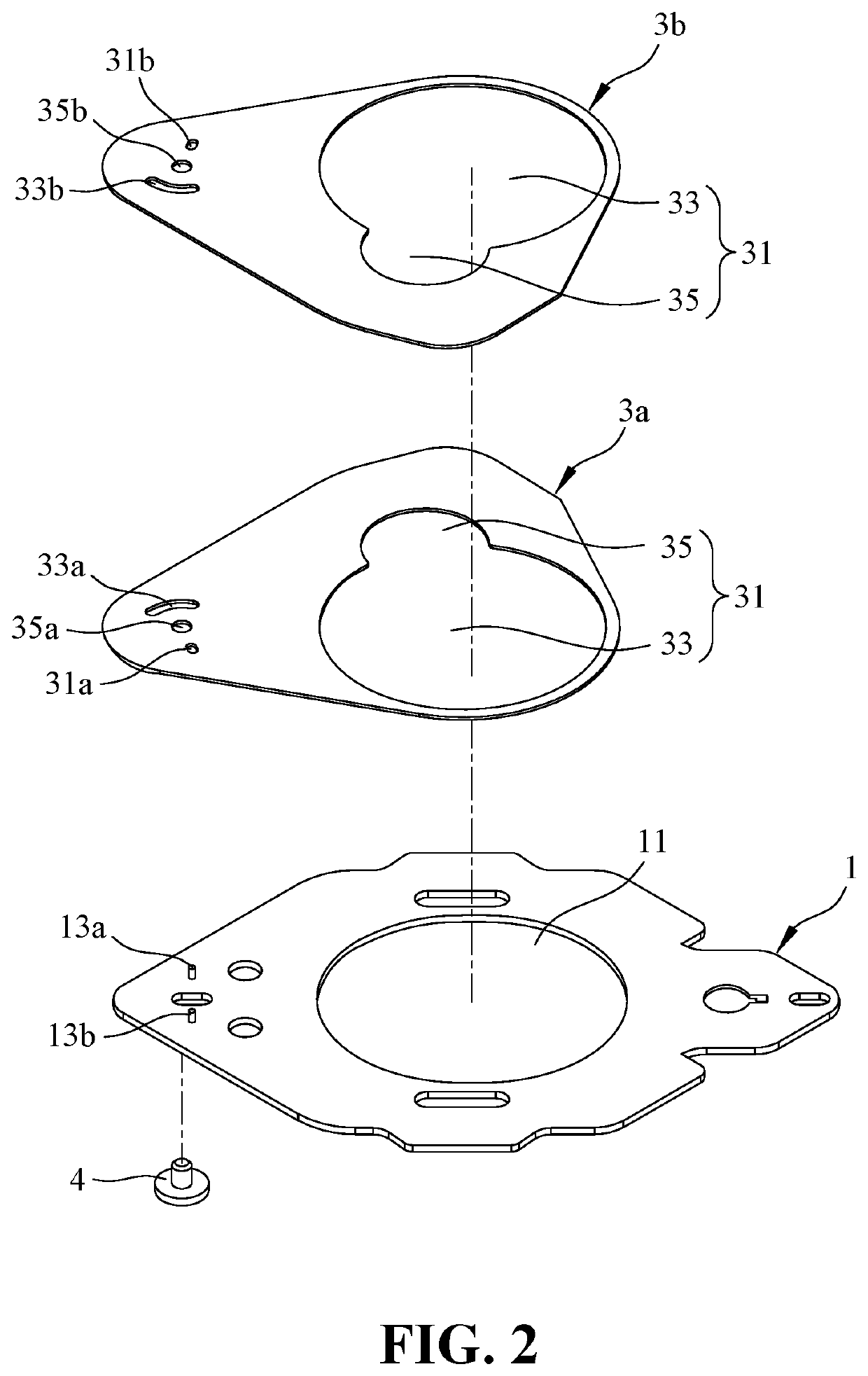
[0028]Referring to FIG. 2, FIG. 2 is an exploded view of two movable diaphragm sheets and the movable plate according to an embodiment. The diaphragm sheet...

second embodiment

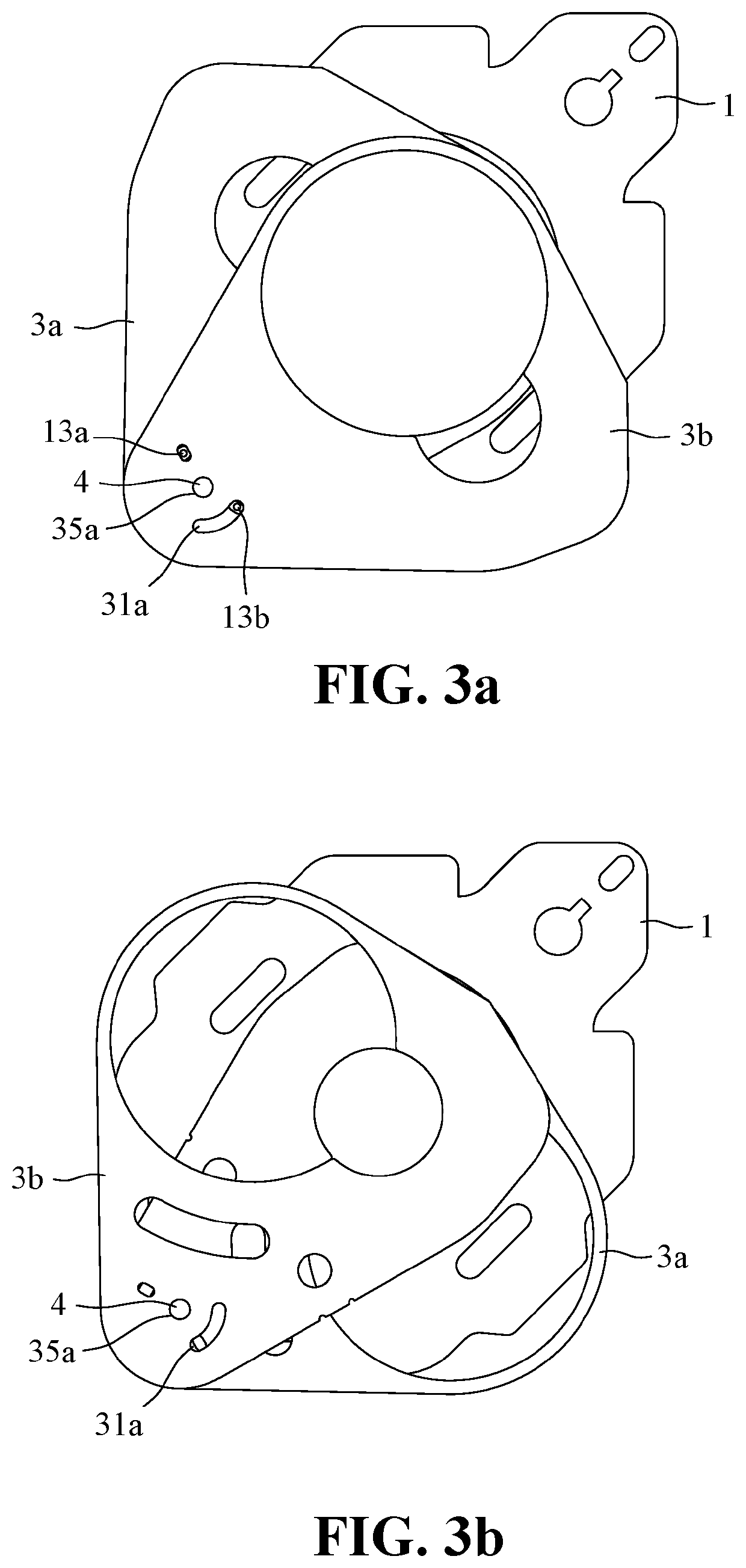
[0030]Each of the two movable diaphragm sheets 3a, 3b has a hollow portion 31. The hollow portion 31 in the second embodiment is composed of a large light through hole 33 and a small light through hole 35 having different opening areas and a part of the large and small light through holes 33 and 35 overlap each other. The large light through hole 33 and the small light through hole 35 are exemplified by a circular shape. Therefore, as viewed from the outer appearance, the hollow portion 31 includes two circular holes which are partially staggered with each other. The two circular holes seem to be incomplete, but in different positions, the hollow portions 31 of the two movable diaphragm sheets 3a, 3b together form a complete two circular holes.

[0031]Specifically, when the movable plate 1 is at the initial position, the two hollow portions of the two movable diaphragm sheets 3a, 3b overlap to the extent that a large (small) light through hole is formed, and at this time, the large (s...

fourth embodiment

[0053]The SMA wire 6 is further electrically connected to an electric device (not shown) so that the SMA wire 6 is thermally deformed to contract after being supplied with the electricity. It should be noted that the V-shape mentioned in the above SMA wire 6 is only for convenience of explaining the fourth embodiment, and therefore is not limited to the V shape, and the V-shaped SMA wire 6 includes a linear body having a sharp bent shape.

[0054]The two ends of the SMA wire 6 are connected to the first fixing member 71 and the second fixing member 73 by crimping or welding.

[0055]The SMA wire 6 is wound around a side of the wire rod 17 away from the first opening 11 so that when the SMA wire 6 is contracted, the wire rod 17 is pushed by the SMA wire 6 to drive the movable plate 1 for moving toward the direction of the first opening 11.

[0056]An outer peripheral surface of the wire rod 17 has a gap structure with a step shape, for example, the diameter of the head of the wire rod 17 is l...


PUM


Abstract

Provided is a diaphragm sheet transfer device, which is used for a handheld electronic device. Diaphragm sheets include different sizes of a plurality of light through holes. By controlling the positions of the diaphragm sheets, the light through holes with different sizes respectively pass through the incident light paths so that the amount of the light incident to the lens device is changed.

Description

BACKGROUND OF THE INVENTION1. Field of the Invention[0001]The present invention relates generally to a diaphragm sheet transfer device, which is specifically used for a handheld electronic device having a camera or recording lens.2. The Prior Arts[0002]Since the advent of smart phones, because smart phones have camera recording capabilities, the public often use the mobile phones instead of cameras to take pictures. The smart phones are continually innovated in the market, and especially the major mobile phone manufacturers adopt the highest pixel, and large diaphragm. However, the diaphragm of the mobile phone is a fixed diaphragm, and it cannot be zoomed in or zoomed out as a normal camera lens.[0003]The zoomed-in or zoomed-out of controlling the diaphragm is to drive the movement of a plurality of diaphragm sheets through a diaphragm motor. However, since the volume of the mobile phone is required to be thin and lightweight, it is not obviously suitable for the diaphragm motor to...

Claims


Application Information

Patent Timeline
IPC IPC(8): G03B9/06
CPCG03B9/06G03B30/00
Inventor CHIU, CHI-WEICHEN, YUNG-YUN
Owner TDK TAIWAN
Why Eureka
Try Eureka