
Pressure relief valve for a packaging container

a pressure relief valve and packaging container technology, applied in the field of pressure relief valves for packaging containers, can solve the problems of high vacuum tightness, high opening pressure of valves with high vacuum tightness, and differences in the distance between the recess and the valve diaphragm, so as to achieve reliable vacuum sealing, simple and economical manner, and high vacuum resistance

Active Publication Date: 2013-10-15
SYNTEGON TECHNOLOGY GMBH
View PDF11 Cites 6 Cited by
  • Summary
  • Abstract
  • Description
  • Claims
  • Application Information

AI Technical Summary

Benefits of technology

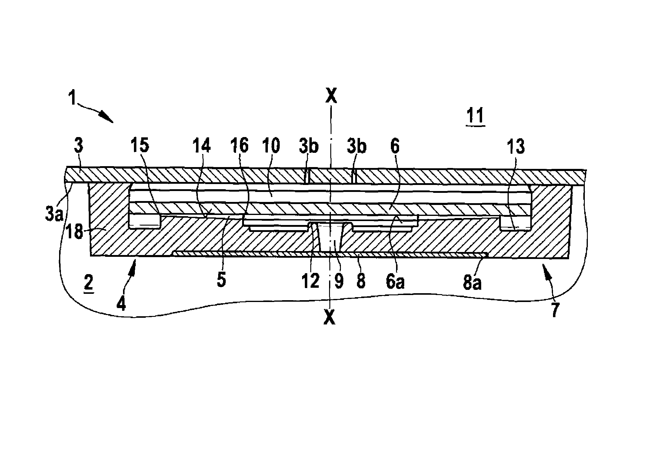
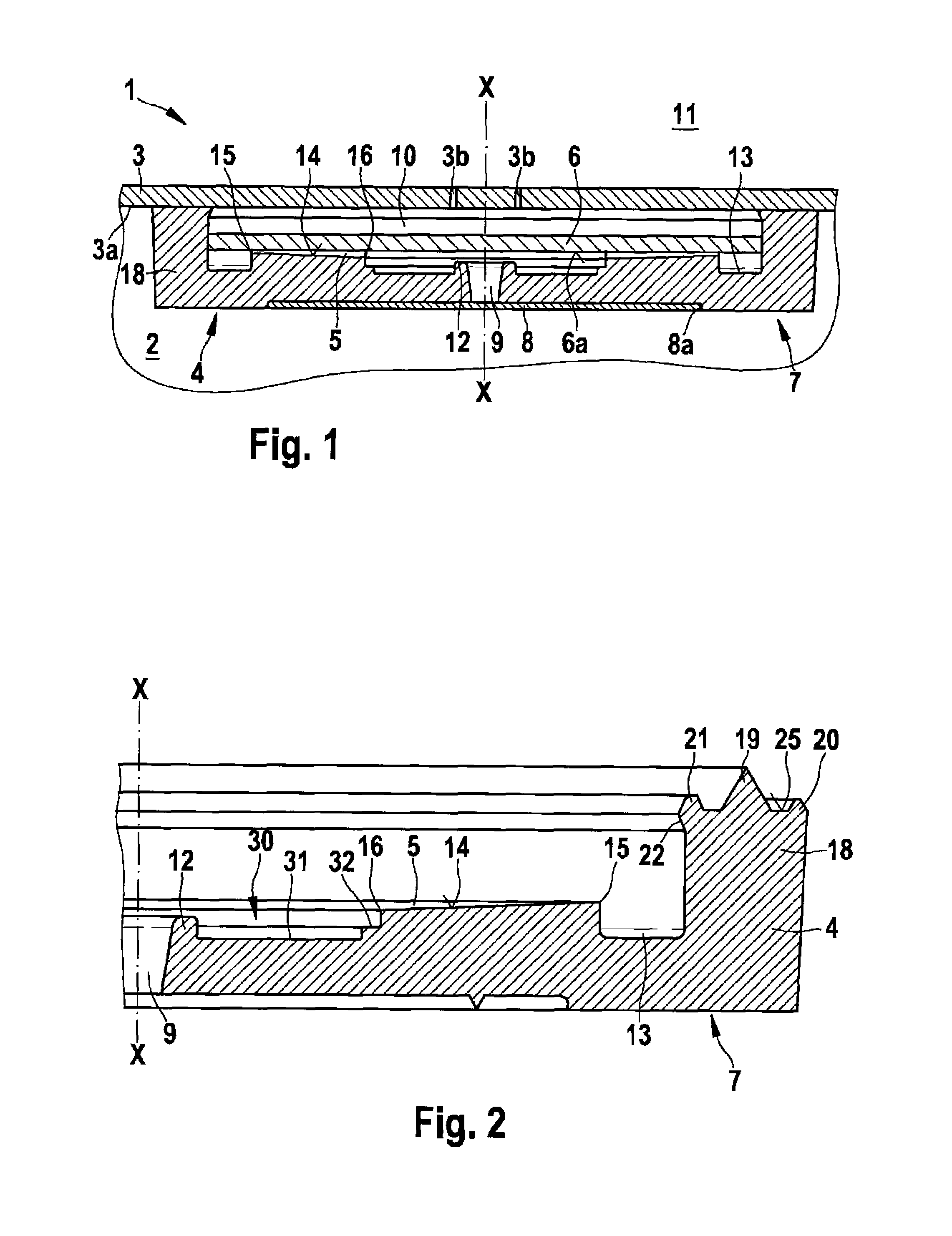
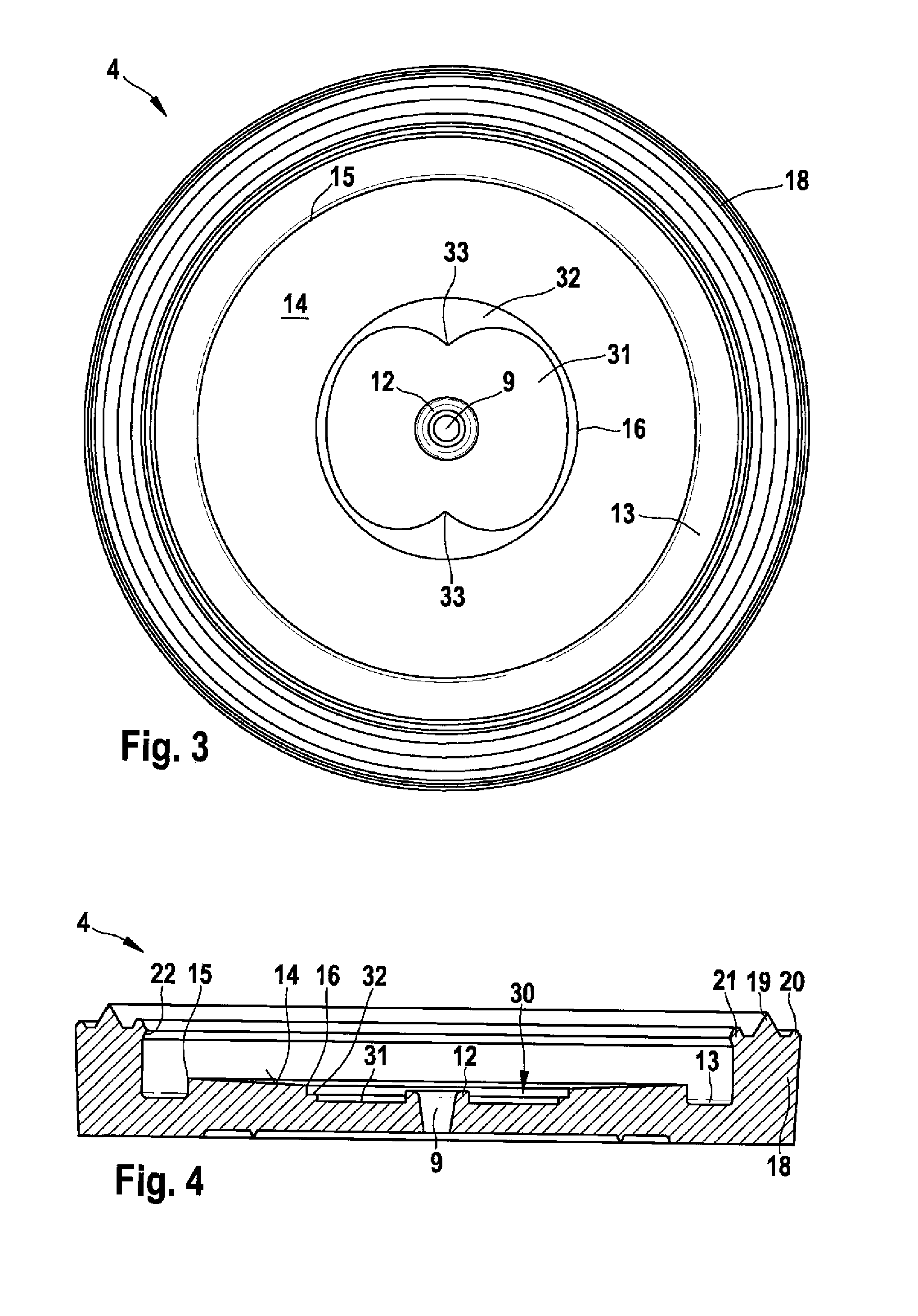
The invention is a pressure relief valve for a packaging container that has a simple and economical construction, and it provides high vacuum resistance and opening even with small pressure differences. It consists of a main body with an inward-tapering sealing surface and a diaphragm that rests on the sealing surface to seal off a central through opening. The opening has an annular bead that ensures reliable sealing of the vacuum in the packaging container. The valve has deformable properties and a retaining device to prevent the diaphragm from coming away unexpectedly. It can be made from materials like rubber, which provides flexibility and sealing properties. The valve has a bottom region with a perforation or a filter element to prevent small particles from entering it. Overall, the invention provides a reliable and efficient solution for releasing pressure in packaging containers.

Problems solved by technology

In practice, however, the two above-mentioned aims are in conflict since, on the one hand, the pressure for opening the valve should only be low and, on the other hand, high vacuum tightness should be provided.
Valves which have a high vacuum tightness therefore also have a very high opening pressure.
This results in differences in the distance between the recess and a valve diaphragm in different zones.

Method used


Image

  • Pressure relief valve for a packaging container
  • Pressure relief valve for a packaging container
  • Pressure relief valve for a packaging container

Examples


Embodiment Construction

[0019]A pressure relief valve 1 in accordance with a preferred illustrative embodiment of the invention is described in detail below with reference to FIGS. 1 to 4.

[0020]As can be seen from FIG. 1, the pressure relief valve 1 comprises a main body 4 and a diaphragm 6. The main body 4 has a sealing surface 14, which tapers conically inward in the direction of a center line X-X. A fluid 5 is arranged between the sealing surface 14 and the diaphragm 6 and forms a thin layer of fluid. This layer of fluid becomes continuously somewhat thicker from an outer edge 15 of the sealing surface 14 to an inner edge 16.

[0021]A filter element 8 is provided in a small recess 8a on a side 7 of the main body 4 which is oriented toward the inner side of a package in the assembled condition. More particularly, the filter element 8 covers a central through opening 9 and prevents small particles from being able to flow into the through opening 9 and thus into the pressure relief valve 1.

[0022]The pressure...


PUM


Abstract

The invention relates to a pressure relief valve for a packaging container (3), comprising a base body (4) with a central through opening (9), a sealing surface (14) and a peripheral region (18), wherein the peripheral region (18) may be sealingly connected to an inner side (3a) of the packaging container (3) and the sealing surface (14) has an inwardly tapering form and a membrane (6), making contact with the sealing surface (14) to permit a seal wherein a fluid (5) is arranged between the sealing surface (14) and the membrane (6). The membrane (6) is flexible and a recess (30) is made in the base body (4) into which the central through opening (9) opens out, wherein in the opening region of the central through opening (9), an annular bead (12) projecting in the direction of the membrane (6) is arranged, projecting into the recess (30).

Description

BACKGROUND OF THE INVENTION[0001]The present invention relates to a pressure relief valve for a packaging container with significantly improved sealing properties.[0002]Various embodiments of pressure relief valves for packaging containers are known from the prior art. The use of valves, especially on flexible packages for foodstuffs, has already been implemented by a large number of technical variants. A principal requirement on valves of this kind is that they should permit only slight excess pressures in the package through appropriate opening and otherwise should reliably prevent the penetration of ambient air. In this context, the penetration of ambient air must be prevented even when the pressure in the package is very low. In practice, however, the two above-mentioned aims are in conflict since, on the one hand, the pressure for opening the valve should only be low and, on the other hand, high vacuum tightness should be provided. Valves which have a high vacuum tightness ther...

Claims


Application Information

Patent Timeline
Patent Type & Authority Patents(United States)
IPC IPC(8): F16K15/14
CPCB65D77/225Y10T137/4358Y10T137/7879Y10T137/7887
Inventor STADEL, HANS-PETERSTOTKIEWITZ, HERBERTHAAK, JUERGEN
Owner SYNTEGON TECHNOLOGY GMBH
Learn More