Pressure actuated ported sub for subterranean cement completions

a technology of ported subsoil and cement, which is applied in the direction of fluid removal, borehole/well accessories, construction, etc., can solve the problems of leaking path potential from the tubing to the annulus, the sleeve gets stuck, and the design cannot be used in cementing applications, so as to avoid flexing or bending

Active Publication Date: 2013-10-15
BAKER HUGHES OILFIELD OPERATIONS LLC
View PDF62 Cites 25 Cited by
  • Summary
  • Abstract
  • Description
  • Claims
  • Application Information

AI Technical Summary

Problems solved by technology

The problem is that to get the lower seal to be smaller than the upper seal to create the desired net force in the needed direction, the wall of the sleeve adjacent the lower seal and the atmospheric chamber has to be reduced so that the sleeve can shift while the volume of the atmospheric chamber is reduced.
When that happens the sleeve gets stuck and the desired port opening in the housing fails to occur.
This design cannot be used in cementing applications as the filling up of the annulus with cement can block access to annulus pressure.
Furthermore, there is a leak path potential from the tubing to the annulus through a piston seal leak.

Method used


Image

  • Pressure actuated ported sub for subterranean cement completions
  • Pressure actuated ported sub for subterranean cement completions
  • Pressure actuated ported sub for subterranean cement completions

Examples


Embodiment Construction

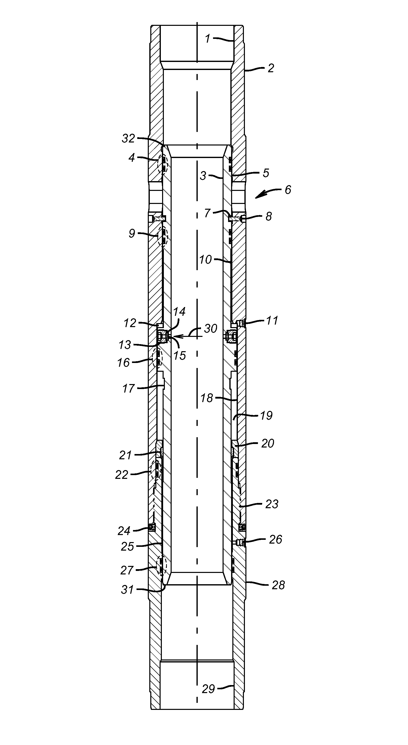
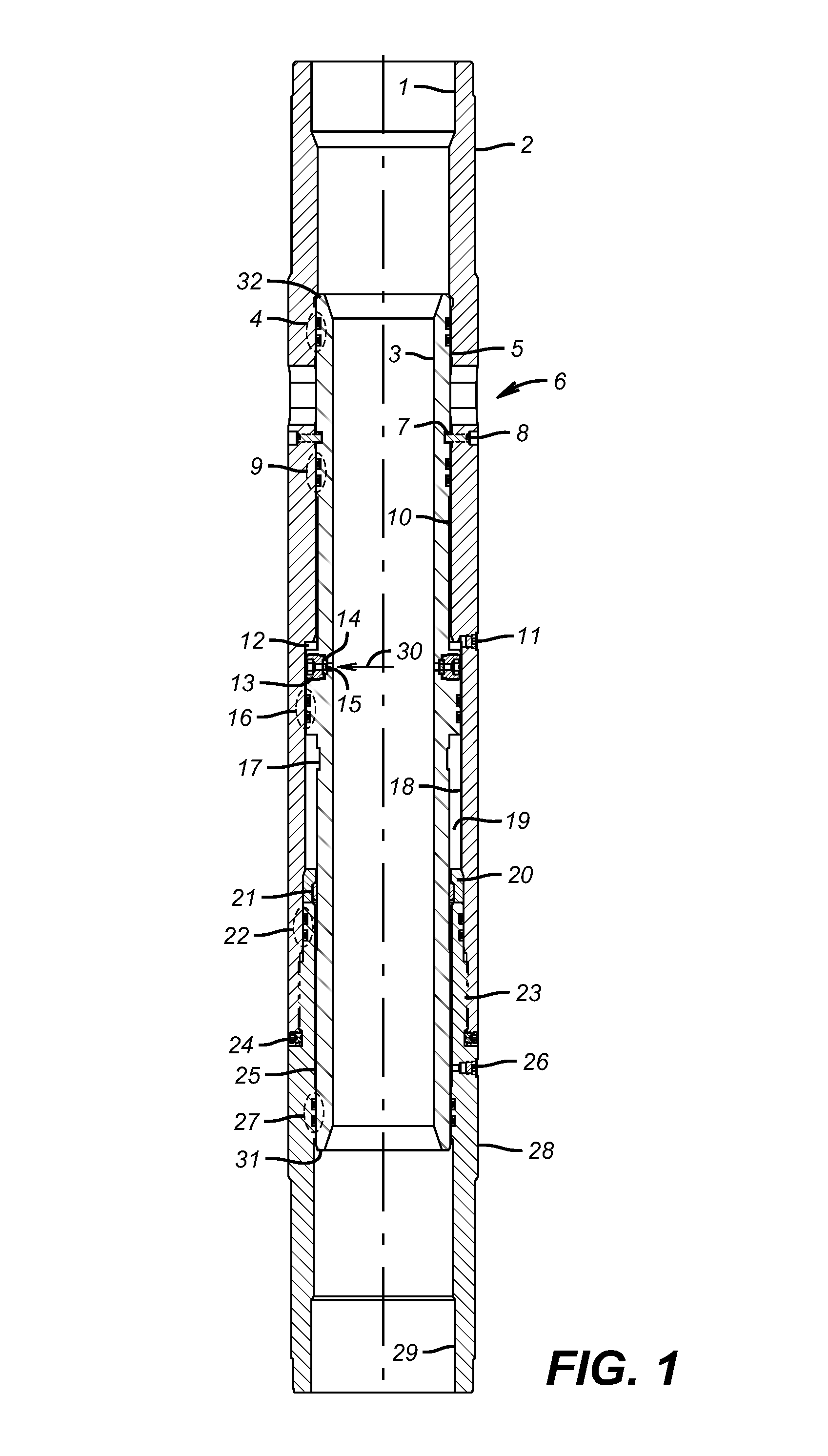
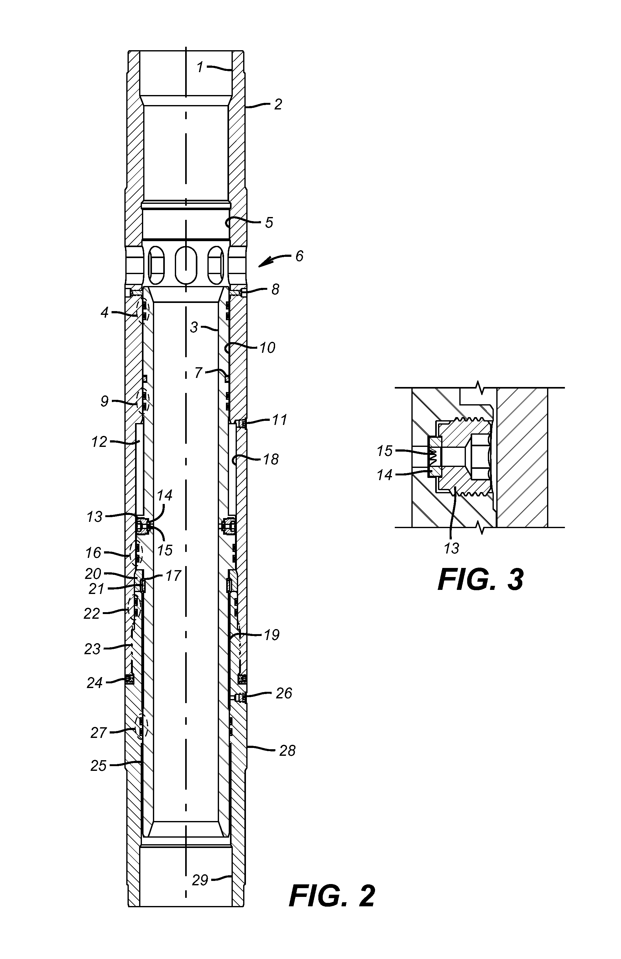
[0011]Referring to FIG. 1, the apparatus has the following components:[0012]upper body tubular connection 1;[0013]upper ported housing 2;[0014]inner shifting sleeve 3;[0015]port isolation seals 4;[0016]upper internal polished bore 5;[0017]fluid communication ports 6;[0018]sleeve shear screw shoulder 7;[0019]shear screws 8;[0020]upper internal bore piston seals 9;[0021]intermediate internal polished bore 10;[0022]upper pressure testing port 11;[0023]upper atmospheric chamber 12;[0024]burst disk load nut 13;[0025]burst disk load ring 14;[0026]burst disk or chemically responsive barrier 15;[0027]intermediate internal bore piston seals and piston 16;[0028]sleeve lock ring retention groove 17;[0029]lower internal polished bore 18;[0030]lower atmospheric chamber 19;[0031]sleeve lock ring retainer 20;[0032]sleeve lock ring 21;[0033]body seals 22;[0034]body connection 23;[0035]body set screws 24;[0036]lower sleeve polished bore 25;[0037]lower pressure testing port 26;[0038]lower external ro...


PUM


Abstract

A tubing pressure operated sliding sleeve is used in cementing a tubular string. The sleeve is configured to hold closed as pressure builds to a predetermined value. When pressure is further raised a rupture disc blows and provides access to an integral piston disposed outside the sleeve. The back side of the piston is exposed to a low pressure or atmospheric chamber located between upper and lower seals. The sleeve thickness near the chamber can be made relatively thick to avoid flexing or bending under differential pressure because the net force to shift the sleeve is from differential pressure on the piston rather than the piston areas created by the upper and lower seals.

Description

FIELD OF THE INVENTION[0001]The field of the invention is a pressure actuated sleeve used in a cementing assembly that is responsive to tubing pressure to open a port and more particularly a sleeve that is associated with a piston where the piston is not referenced to annulus pressure when actuated by selective communication of tubing pressure to one side with the opposed side referenced to a low pressure chamber within the housing.BACKGROUND OF THE INVENTION[0002]Prior sleeves that have been deployed in cementing service have been based on the concept of providing opposed piston areas exposed to tubing pressure that are of different dimensions so that raising the tubing pressure will create a sufficient net force to in theory overcome seal friction and move the sleeve to the open position. One such design is the Halliburton Initiator Sliding Sleeve that has a larger upper seal diameter than a lower seal. Raising tubing pressure creates a net differential force and the piston is all...

Claims


Application Information

Patent Timeline
Patent Type & Authority Patents(United States)
IPC IPC(8): E21B34/08
CPCE21B34/063E21B34/10E21B33/14E21B2034/007E21B2200/06
Inventor MAILAND, JASON C.KELLNER, JUSTIN C.JONHSON, CHARLES C.KIRKPATRICK, CHARLES T.AVANT, MARCUS A.
Owner BAKER HUGHES OILFIELD OPERATIONS LLC
Why Eureka
Try Eureka