Damping system for steering wheel

a technology of steering wheel and damping system, which is applied in the direction of steering parts, pedestrian/occupant safety arrangement, vehicle components, etc., can solve the problems of complex and troublesome mounting work of elastic members in mounting holes, affecting the comfort of driving drivers, and deteriorating driving comfort of drivers. , to achieve the effect of facilitating elastically deformation

Active Publication Date: 2013-10-15
TOYODA GOSEI CO LTD
View PDF10 Cites 25 Cited by
  • Summary
  • Abstract
  • Description
  • Claims
  • Application Information

AI Technical Summary

Benefits of technology

[0017]The invention has been made in view of these circumstances, and an object thereof is to provide a damping system for steering wheel which can mount an elastic member in a state of restricting the movement thereof by simple work.
[0019]In the damping system for steering wheel which is configured in the way described above, the airbag device functions as the damper mass of the dynamic damper, and the elastic member functions as the spring of the dynamic damper. Because of this, when the steering wheel vibrates with a predetermined frequency in a direction perpendicular to the steering shaft, the elastic member vibrates together with the airbag device in the direction perpendicular to the steering shaft (the airbag device and the elastic member resonate) so as to absorb the vibration energy of the steering shaft. By absorbing the vibration energy in this way, the vibration of the steering wheel is suppressed (controlled).
[0025]As a result, the airbag device and the elastic member are allowed to vibrate as designed while facilitating the mounting work of the elastic member, thereby making it possible to exhibit the vibration controlling effect.
[0027]According to the configuration described above, the groove portion which is opened in at least one of the front surface and the rear surface of the elastic member facilitates the elastic deformation of the elastic member. Because of this, when the steering wheel vibrates, the elastic member is allowed to resonate easily together with the airbag device, whereby it becomes easier to obtain the suppressing (controlling) effect of the vibration of the steering wheel.
[0030]In the third aspect, by forming the groove portion between the engaging portion and the slider, the portion in relation to the elastic deformation is made to be elastically deformed more easily, whereby the effect provided in the second aspect can be obtained more easily.

Problems solved by technology

When vibrations are transmitted to a steering wheel in a vertical direction and a horizontal direction while the vehicle is being driven at high speed or an in-vehicle engine is idling, the comfortable driving of the driver may be deteriorated.
Therefore, in recent steering wheels, it becomes difficult to incorporate the dynamic damper in the steering wheel.
Therefore, the mounting work of the elastic member in the mounting hole becomes complex and troublesome.
In addition, in the configuration, it becomes difficult to mount the elastic member in the mounting hole without a gap between an inner bottom surface of the annular groove and an inner wall surface of the circular mounting hole.
When such a gap is produced, an airbag module and the elastic body do not vibrate as designed, which may not provide the intended vibration control effect.
In particular, since the direction in which the circular mounting hole is fitted in the annular groove and the direction in which the damper mass (the airbag module) and the spring (the elastic body) of the dynamic damper vibrate to reduce vibrations are the same directions perpendicular to the steering shaft, the above-described problem with the gap is likely to be occur.

Method used


Image

  • Damping system for steering wheel
  • Damping system for steering wheel
  • Damping system for steering wheel

Examples


Embodiment Construction

[0046]Hereinafter, referring to the drawings, an embodiment of the invention will be described in which the invention is embodied in a damping system for a steering wheel of a vehicle.

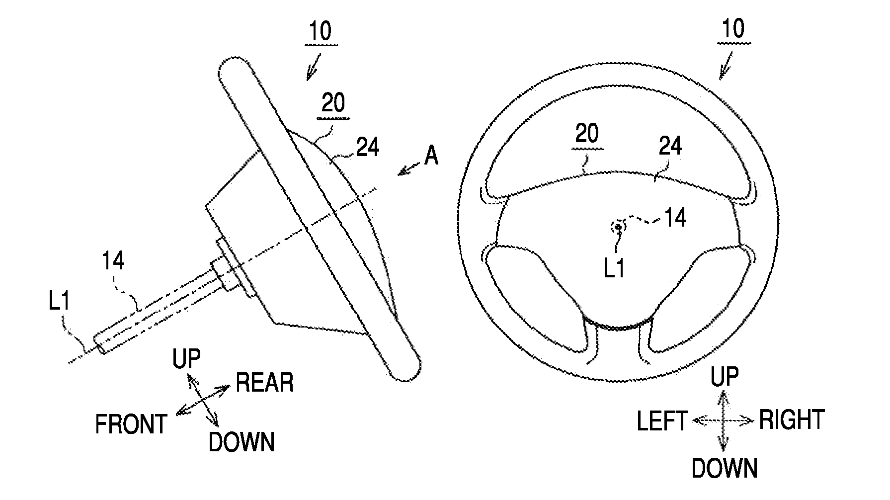
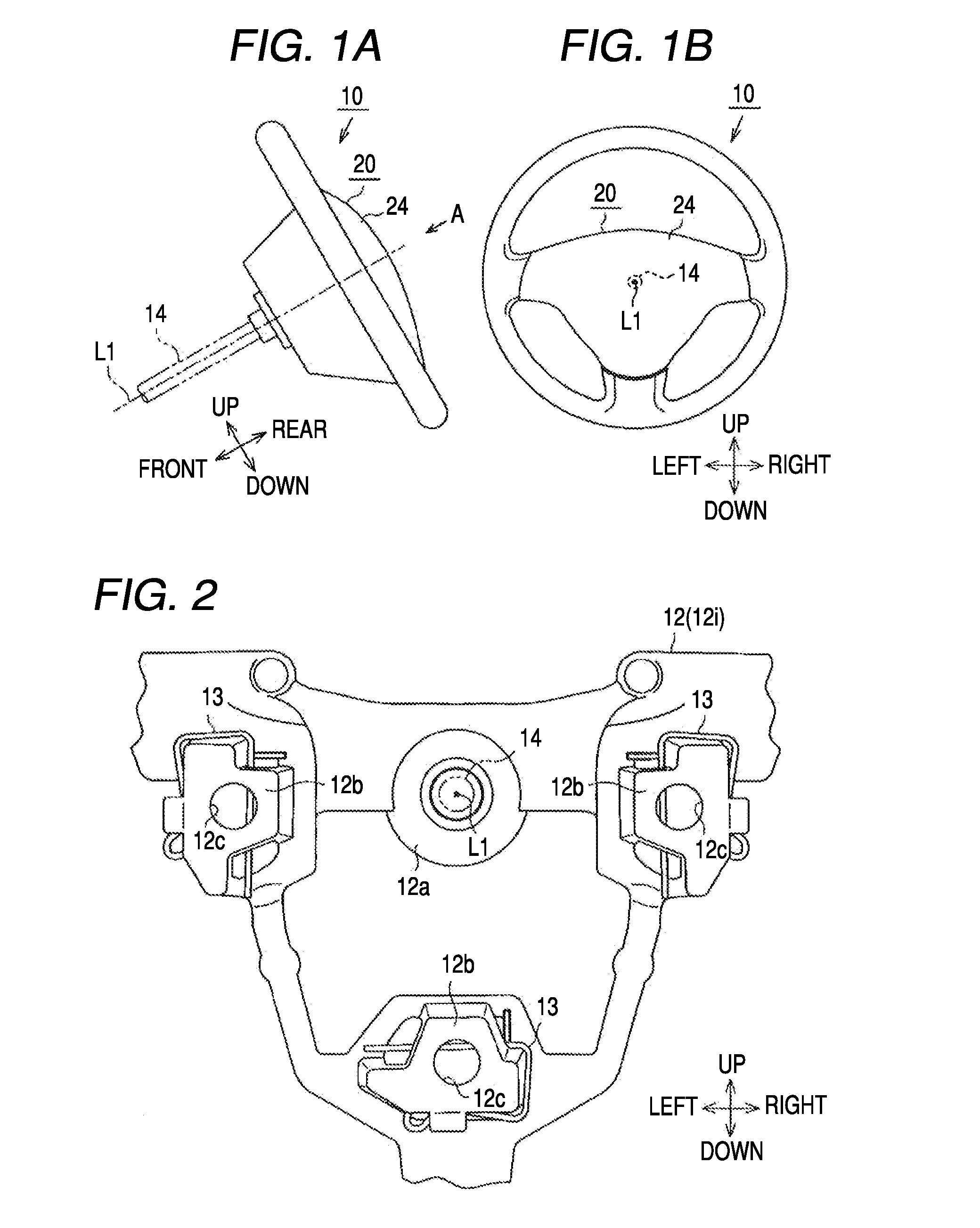
[0047]As shown in FIG. 1A, a steering shaft 14 which extends along an axis L1 in a front-rear and which rotates about the axis L1 is mounted in a position in a vehicle which lies further forwards (leftwards in FIG. 1A) than a driver's seat so as to be inclined so that an end (a right end in FIG. 1A) of the steering shaft which lies to face the driver's seat gets higher. A steering wheel 10 according to this embodiment is mounted at a rear end portion of the steering shaft 14 so as to rotate together with the steering shaft 14.

[0048]In this embodiment, when describing them, constituent portions of the steering wheel 10 will be described based on the axis L1 of the steering shaft 14. A direction which follows the axis L1 is referred to as a “front-rear,” and in directions perpendicular to the axis L1, a ...


PUM


Abstract

A damping system includes: a fixed member; an airbag device including a back holder and disposed on a rear side of the fixed member; an elastic member mounted in a mounting hole of the back holder; and a horn switch mechanism including a support member supported on the fixed member on a front side of the back holder, and a slider disposed between the support member and the elastic member. The airbag device functions as a damper mass of a dynamic damper, and the elastic member functions as a spring thereof. The horn switch mechanism includes an extended portion extending forwards. An engaged portion is formed at a circumferential edge portion of the mounting hole to extend rearwards. The elastic member includes an engaging portion opened in a front surface thereof. The elastic member is sandwiched by the engaged portion fitted in the engaging portion and the extended portion.

Description

BACKGROUND[0001]1. Technical Field[0002]The present invention relates to a damping system for suppressing (controlling) vibrations of a steering wheel which incorporates an airbag device.[0003]2. Background Art[0004]When vibrations are transmitted to a steering wheel in a vertical direction and a horizontal direction while the vehicle is being driven at high speed or an in-vehicle engine is idling, the comfortable driving of the driver may be deteriorated. For this reason, techniques for suppressing (controlling) the vibrations of a steering wheel have been developed and proposed. One of the techniques employs a dynamic damper including a damper mass and an elastic member which supports the damper mass on a metallic core frame of the steering wheel. According to this technique, when vibrations of a frequency which is the same as or close to a resonance frequency specific to the dynamic damper are transmitted from the steering wheel to the dynamic damper, the dynamic damper resonates...

Claims


Application Information

Patent Timeline
Patent Type & Authority Patents(United States)
IPC IPC(8): B60R21/16
CPCB60R21/203B62D7/222B60R21/2037B60Q5/003
Inventor UMEMURA, NORIOISHII, TSUTOMUSHIGETA, KOSUKEHIROSE, OSAMU
Owner TOYODA GOSEI CO LTD
Why Eureka
Try Eureka