
Radiography apparatus including a mode selection unit for selecting a tomosynthesis mode based on region being radiographed

a radiograph and mode selection technology, applied in the field of radiograph apparatus, can solve the problems of reducing the quality of the reconstructed slice image, the movement of the x-ray detector, and the inability to obtain an image of desirable quality and a slice image including the region of interest, so as to increase the size of the reconstructable region

Inactive Publication Date: 2013-10-15
FUJIFILM CORP
View PDF16 Cites 15 Cited by
  • Summary
  • Abstract
  • Description
  • Claims
  • Application Information

AI Technical Summary

Benefits of technology

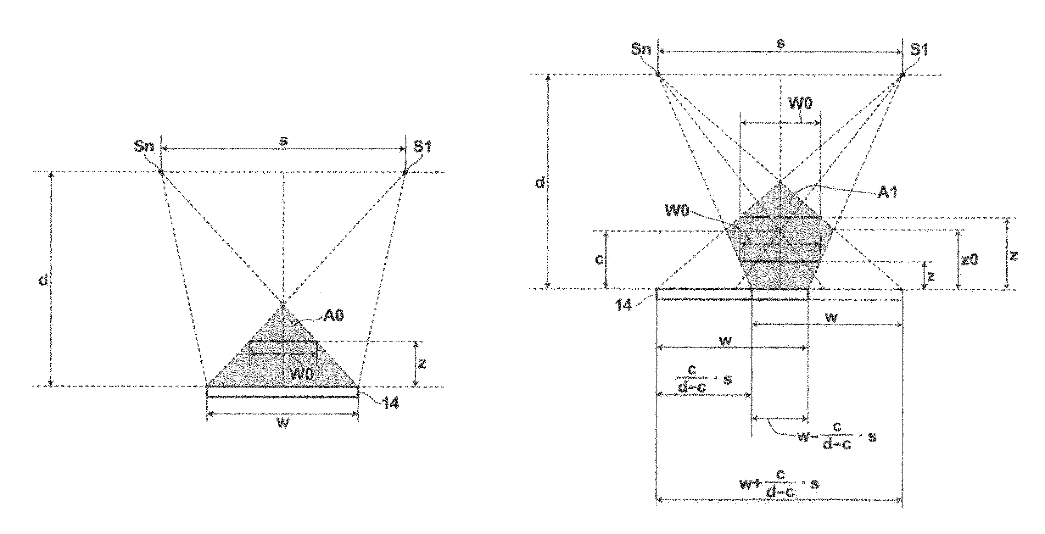
The present invention relates to a tomosynthesis radiography system that can obtain an appropriate slice image based on the condition of radiography without imposing a heavy burden on an operator. The system can select between two modes: the first mode in which only the radiation source is moved or the second mode in which both of the radiation source and the detection means are moved. When the radiation source and the detection means are moved relative to each other in the second mode, it is possible to increase the size of a reconstructable region compared with the first mode. This results in a wider range of body parts that can be imaged using the tomosynthesis system and reduces the burden on the operator.

Problems solved by technology

However, when both of the X-ray tube and the X-ray detector are moved, if the X-ray detector is not moved accurately, the position of an object (target) projected onto a radiographic image shifts or the like, and there is a problem that the quality of a reconstructed slice image drops.
In contrast, when only the X-ray tube is moved, the problem caused by the movement of the X-ray detector does not arises.
Therefore, if the operator selects a mode that is not appropriate for the condition of radiography, it becomes impossible to obtain an image of desirable quality and a slice image including the region of interest.
However, such operation of checking the mode every time of radiography imposes a heavy burden on the operator.

Method used


Image

  • Radiography apparatus including a mode selection unit for selecting a tomosynthesis mode based on region being radiographed
  • Radiography apparatus including a mode selection unit for selecting a tomosynthesis mode based on region being radiographed
  • Radiography apparatus including a mode selection unit for selecting a tomosynthesis mode based on region being radiographed

Examples


first embodiment

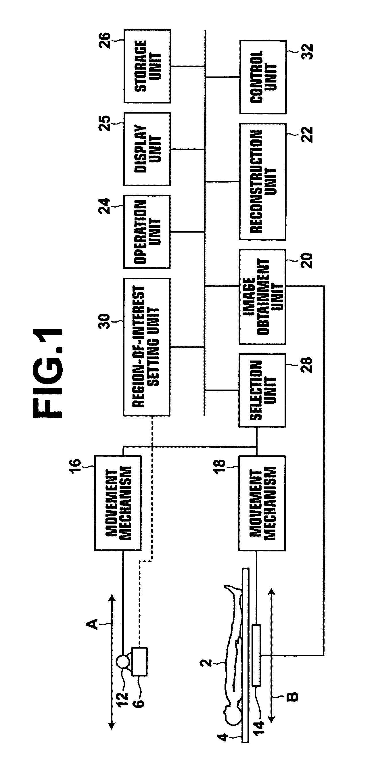
[0037]Hereinafter, embodiments of the present invention will be described with reference to drawings. FIG. 1 is a schematic diagram illustrating an X-ray radiography apparatus to which a radiography apparatus according to the present invention has been applied. As illustrated in FIG. 1, an X-ray radiography apparatus 10 according to the present embodiment includes an X-ray tube 12 and a flat-panel X-ray detector (hereinafter, simply referred to as a detector) 14. The X-ray tube 12 is moved straight or along an arc or curve by a movement mechanism 16. The X-ray tube 12 outputs, at a plurality of positions on the movement path thereof, X-rays to a subject 2 on the top board 4 of a radiographic table. In the present embodiment, it is assumed that the X-ray tube 12 moves along a straight line in the direction of arrow A. The dose of radiation of X-rays output to the subject 2 is controlled by a control unit, which will be described later, so that the dose of radiation becomes a predeter...

second embodiment

[0058]In the second embodiment, the selection unit 28 compares the region of interest that has been set by the region-of-interest setting unit 30 with the reconstructable region in the first mode. If the region of interest that has been set by the region-of-interest setting unit 30 is included in the reconstructable region in the first mode, the selection unit 28 selects the first mode. However, if the region of interest that has been set by the region-of-interest setting unit 30 is not included in the reconstructable region in the first mode, in other words, if the set region of interest is larger than the reconstructable region in the first mode, the selection unit 28 selects the second mode.

[0059]Next, processing performed in the second embodiment will be described. FIG. 8 is a flow chart illustrating the processing performed in the second embodiment. First, the control unit 32 receives setting of the range with respect to the depth direction and the range with respect to the in-...

third embodiment

[0062]In the third mode, the detector 14 is moved to a plurality of positions, and the detector 14 is fixed at each of the plurality of positions. Then, only the X-ray tube 12 is moved while the detector 14 is fixed at each of the positions. FIGS. 9 and 10 are diagrams for explaining the third mode. In FIGS. 9 and 10, the detector 14 is moved from a position to the other position, in other words, the detector 14 is moved to be located at two different positions. Needless to say, the detector 14 may be moved to be located at three or more different positions. In the third embodiment, the detector 14 is moved in such a manner that an edge of the detector 14 located at each position overlaps with an edge of the detector 14 located at the next position by a predetermined amount. First, in the first radiography illustrated in FIG. 9, the detector 14 is moved to a first position that is close to position Sn, and the detector 14 is fixed at the first position. While the detector 14 is fixe...


PUM


Abstract

A radiation source and a detection means are moved relative to each other, thereby moving the radiation source to a plurality of positions. A subject is irradiated with radiation from the plurality of positions to obtain a plurality of radiographic images of the subject. A slice image of the subject is reconstructed from the plurality of radiographic images. At this time, a first mode for moving only the radiation source or a second mode for moving both of the radiation source and the detection means is selected based on the condition of radiography, and the plurality of radiographic images are obtained in the selected mode.

Description

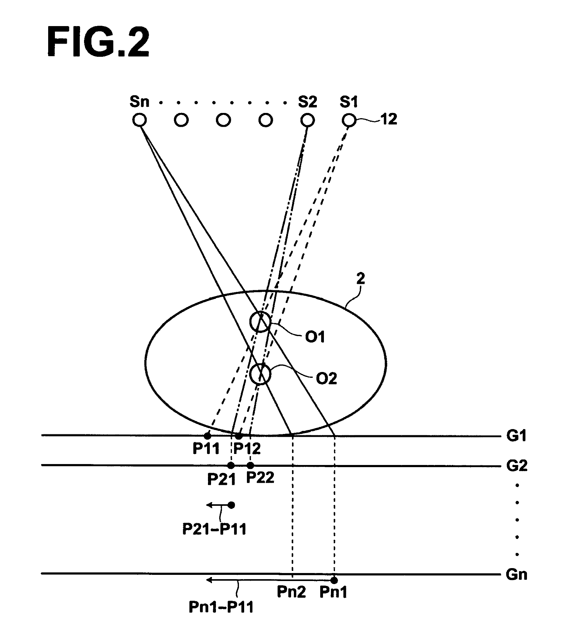
CROSS-REFERENCE TO RELATED APPLICATIONS[0001]The present application claims priority from Japanese Patent Application No. 2009-222250, filed Sep. 28, 2009, the contents of which are herein incorporated by reference in their entirety.BACKGROUND OF THE INVENTION[0002]1. Field of the Invention[0003]The present invention relates to a radiography apparatus for performing tomosynthesis radiography to generate slice images of a subject.[0004]2. Description of the Related Art[0005]In recent years, tomosynthesis radiography was proposed to observe affected regions of patients in more detail by a radiography apparatus using X-rays. In tomosynthesis radiography, radiography is performed by moving an X-ray tube to different positions, and by irradiating a subject by the X-ray tube at different angles from the different positions. Further, images obtained by radiography are added to obtain an image in which a desired cross section of the subject is emphasized. In tomosynthesis radiography, the X...

Claims


Application Information

Patent Timeline
Patent Type & Authority Patents(United States)
IPC IPC(8): H05G1/60H05G1/64
CPCA61B6/032A61B6/06A61B6/469A61B6/542
Inventor AKAHORI, SADATO
Owner FUJIFILM CORP
Learn More