
Brake servo

a technology of brake servo and servo body, which is applied in the direction of servomotors, braking systems, transportation and packaging, etc., can solve the problems of already known brake servo with regard to response and noise characteristics, and achieve the effect of improving controllability and noise characteristics of brake servo and improving low electrical curren

Active Publication Date: 2013-10-22
CONTINENTAL TEVES AG & CO OHG
View PDF8 Cites 2 Cited by
  • Summary
  • Abstract
  • Description
  • Claims
  • Application Information

AI Technical Summary

Benefits of technology

[0004]It is therefore an object of the present invention to further develop a brake servo of the type mentioned in the introduction in such a way that the abovementioned disadvantages are avoided.
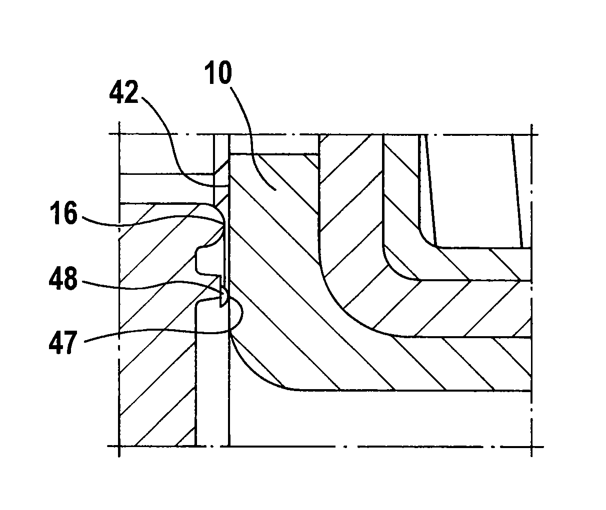
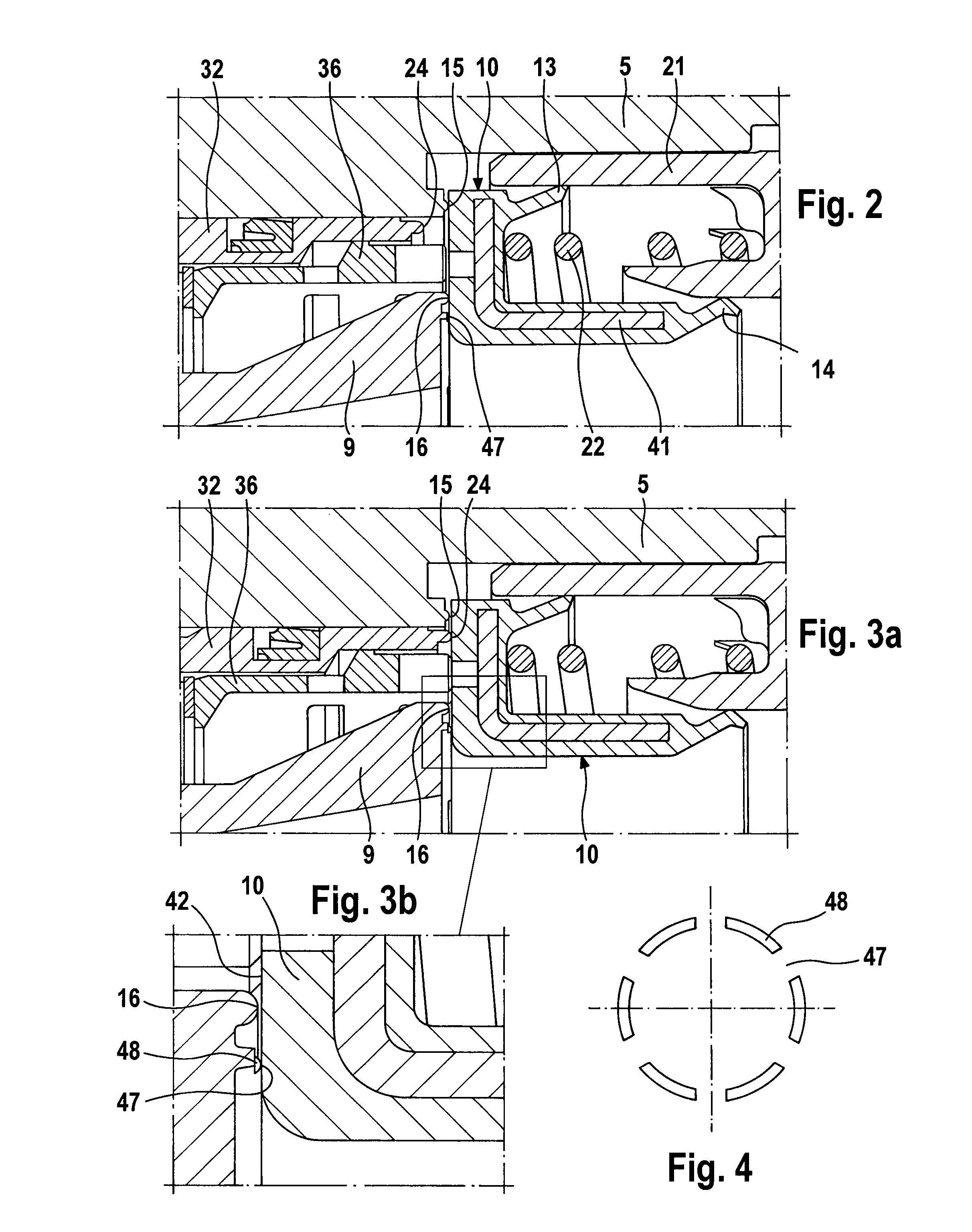
[0006]Those partial regions which project beyond the second sealing seat in the axial direction serve to provide throttling of the air flow at small opening travels of the valve piston, as a result of which the controllability and the noise characteristics of the brake servo when the latter is supplied with low electrical currents are improved.

Problems solved by technology

It has however been found that the already-known brake servo has disadvantages with regard to the response and noise characteristics in the event of the electromagnet being supplied with a low current and at the small opening travel of the valve piston thereby initiated.

Method used


Image

  • Brake servo
  • Brake servo
  • Brake servo

Examples


Embodiment Construction

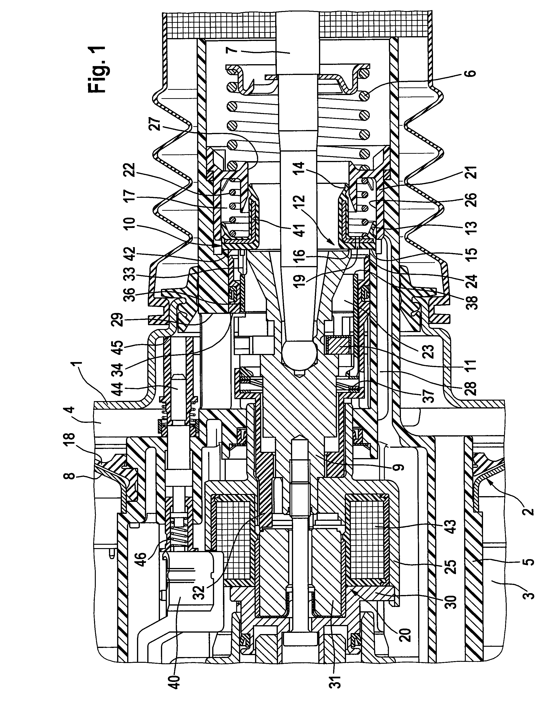
[0016]For better understanding of the invention, the basic design of a brake servo in longitudinal section, such as is known from WO 2006 / 005742 A1, will firstly be explained below on the basis of FIG. 1, before a detailed description is given of the features of the invention shown in FIGS. 2-8 which contribute to the improvement of the proposed brake servo. FIG. 1 shows the servo housing 1 of the known brake servo in sections, which servo housing 1 is divided by an axially movable wall 2 into a vacuum chamber 3 and a working chamber 4. The axially movable wall 2 is composed of a diaphragm plate 8, which is deep-drawn from sheet metal, and a flexible diaphragm 18 which bears against said diaphragm plate 8 and which, in a manner which is not illustrated, forms a rolling diaphragm as a seal between the outer circumference of the diaphragm plate 8 and the servo housing 1.

[0017]A control valve 12 which can be actuated by an actuating rod 7 is accommodated in a control housing 5 which is...


PUM


Abstract

A brake servo whose valve piston has a concentric sealing seat which projects axially beyond a second sealing seat, with the concentric sealing seat having at least one recess for throttling the air volume flow. The controllability and also the noise characteristics of the brake servo can be improved in this way.

Description

CROSS REFERENCE TO RELATED APPLICATIONS[0001]This application is the U.S. national phase application of PCT International Application No. PCT / EP2008 / 065888, filed Nov. 20, 2008, which claims priority to German Patent Application No. DE 10 2007 056 523.4, filed Nov. 22, 2007, and German Patent Application No. 10 2008 037 048.7, filed Aug. 8, 2008, the contents of such applications being incorporated herein by reference.FIELD OF THE INVENTION[0002]The invention relates to a brake servo for motor vehicles, having a servo housing, the interior space of which is divided by a movable wall into a vacuum chamber and a working chamber, and also having a control housing which bears the movable wall and in which is arranged a control valve which controls a pneumatic pressure difference acting on the movable wall and which can be actuated both by an actuating rod via a valve piston and also, independently of the actuating rod, by an electromagnet and which is composed of three sealing seats arr...

Claims


Application Information

Patent Timeline
Patent Type & Authority Patents(United States)
IPC IPC(8): B60T13/57B60T13/72
CPCB60T13/57B60T13/72
Inventor ICKLER, VOLKERKOLLERS, MICHAELKRAEMER, HORSTKREBS, STEPHANKONIG, HARALDJAKOBI, RALFNEU, THORSTEN
Owner CONTINENTAL TEVES AG & CO OHG
Learn More